In one of my other classes, Hacking Audio Hardware, our midterm project is
to create a device that produces noise using gates and oscillators. On this
device, I plan to have four separate variable resistors. My plan for an
application is to combine these projects and create a visual representation
of the different values that the variable resistors are producing. If I can’t
connect it to my gate chip, then I’d like to connect the Arduino with MaxMSP.
Also, this coming weekend I am taking a one credit course called Textile
Interfaces, and I hope to incorporate something from that with this project
as well.
I’m not sure exactly what kind of image I want to manipulate using four
different values, but some initial ideas I have were to use the variable
resistors to draw squares, change the sizes, or maybe the color(s).
Prototyping
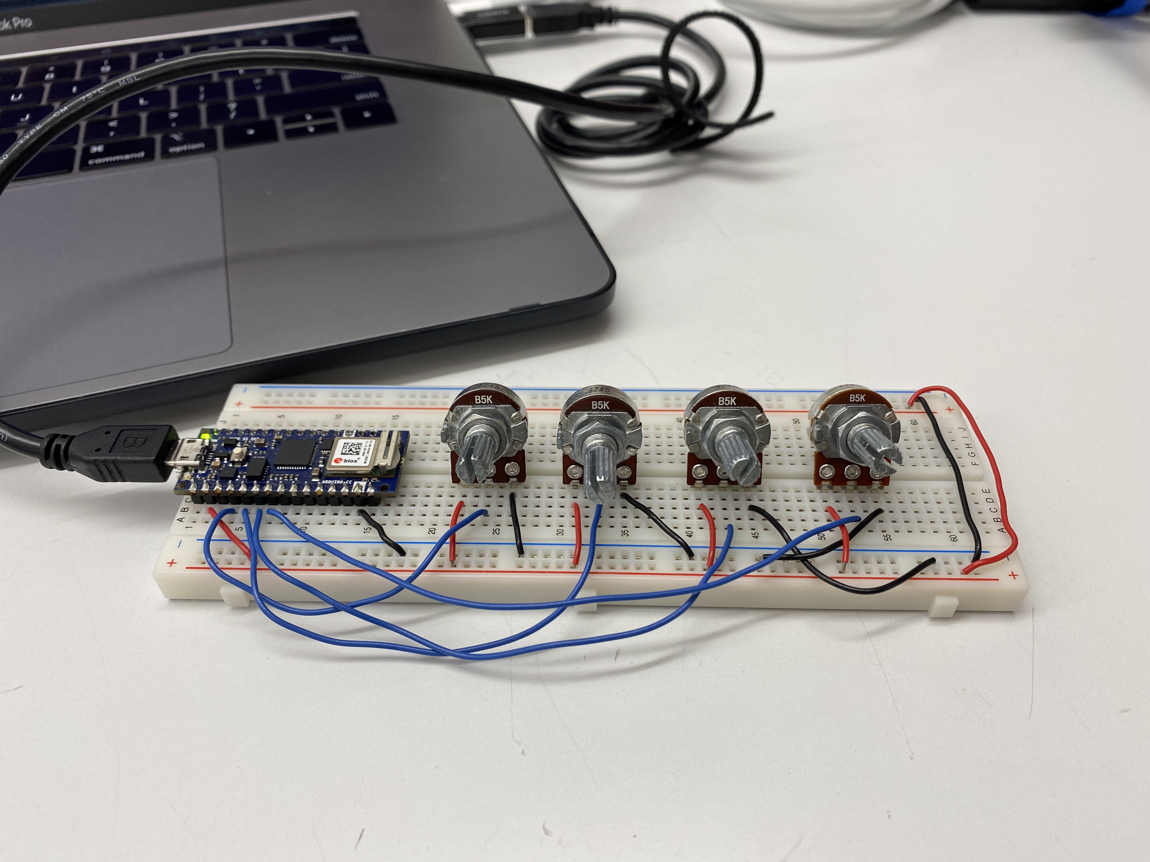
I started off with one potentiometer, and a simple draw sketch to see if I
could manipulate one variable.
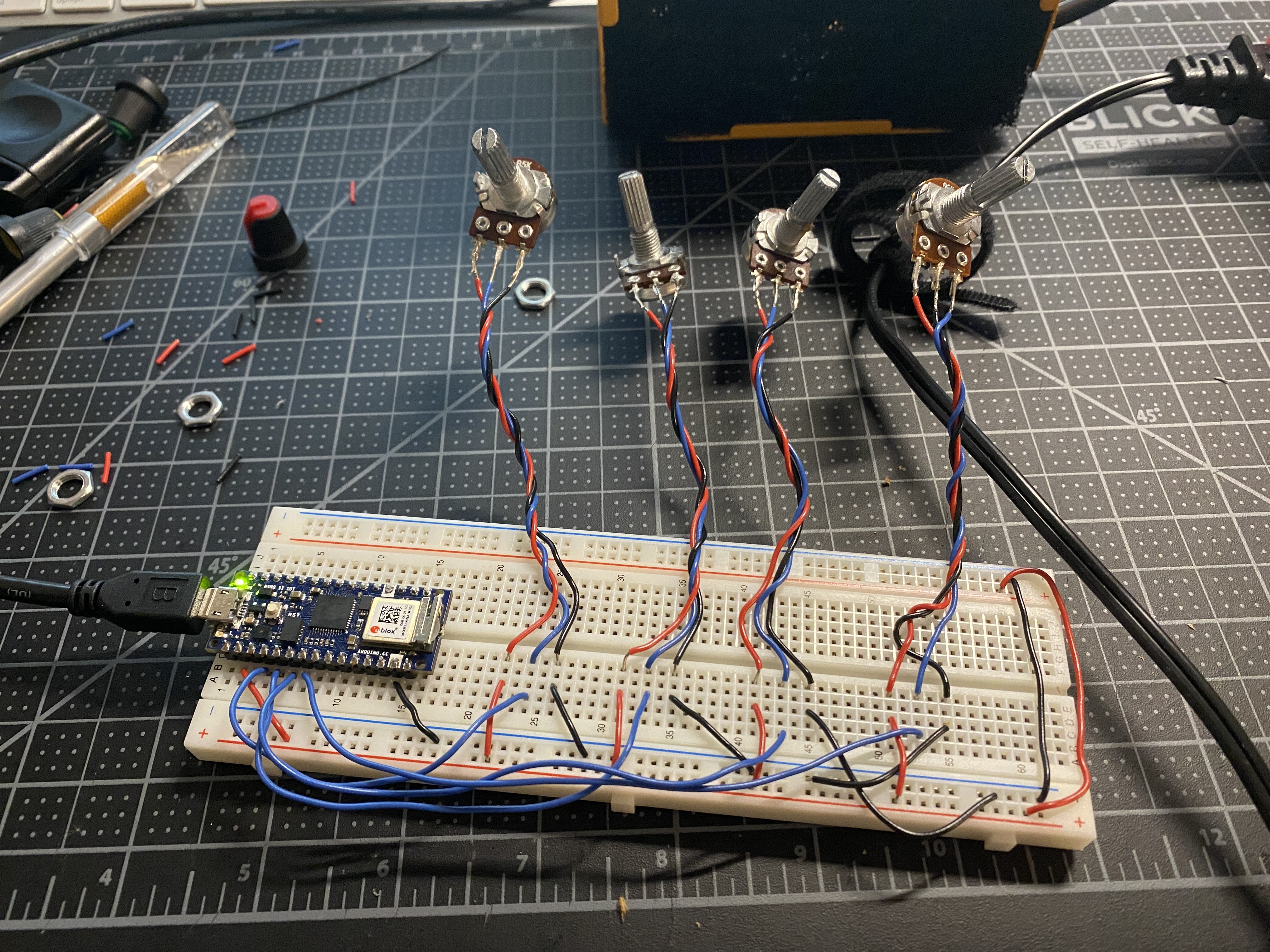
Next, I added three more potentiometers for a total of four variable resistors.
I made each of them affect different elements – the number of
squares/circles, and changing the values for RGB.
Below is the Arduino code. I would also like to add a pushbutton into the
circuit to control another aspect of the visualization.
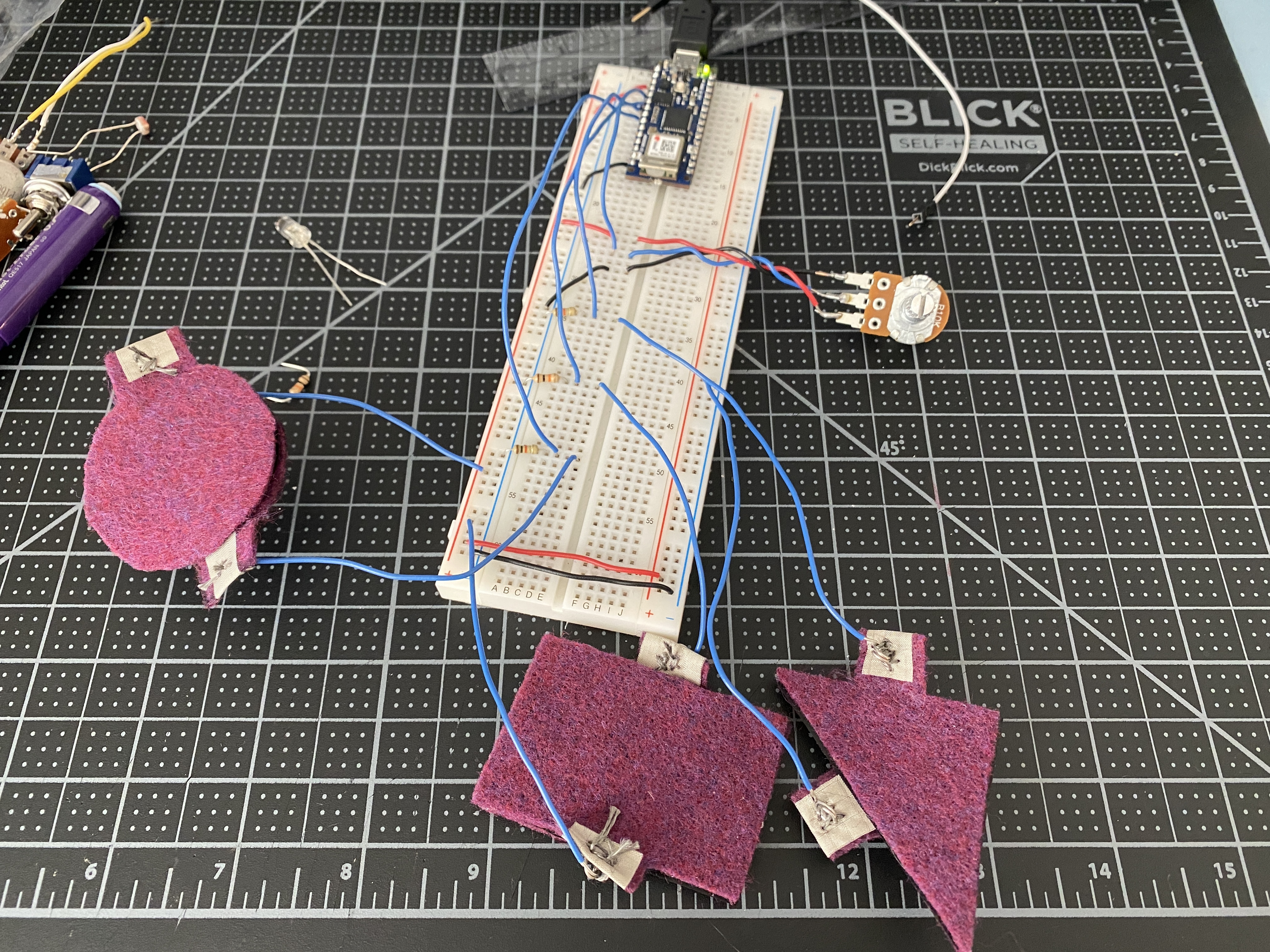
Over Halloween weekend I took a 1-credit course called Textile Interfaces
where we learned to create buttons, digital switches, and circuits using
conductive fabric, thread, and velostat. I’d like to incorporate these textile
sensors into my project, and so below I have three textile sensors along with
a potentiometer controlling different variables in my P5 sketch.
I played around with my P5 code to create something other than simple
rectangles and ellipses. I used a class I created in ICM that makes arcs by
setting parameters for its location, the max size, step size/density, and color.
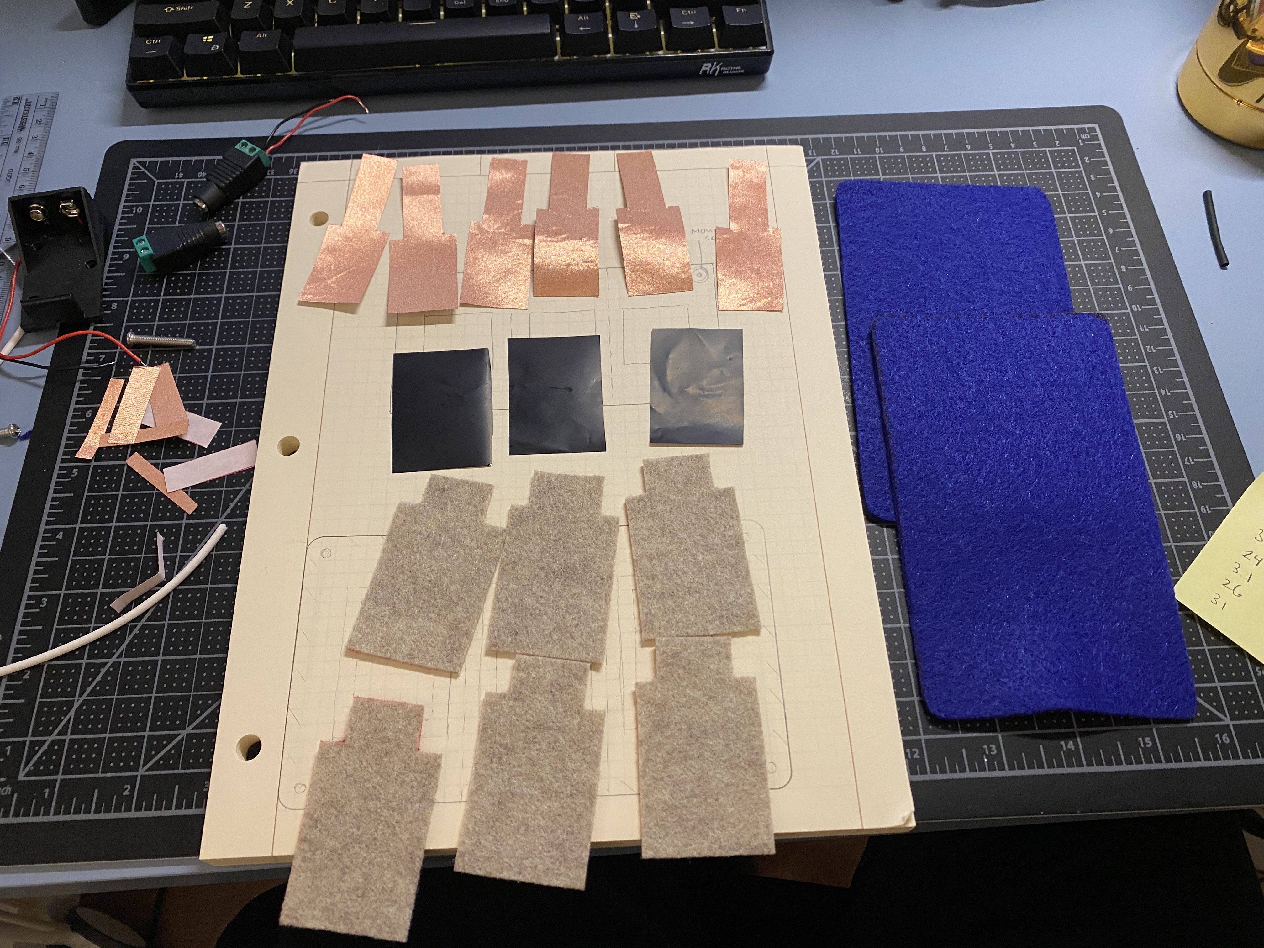
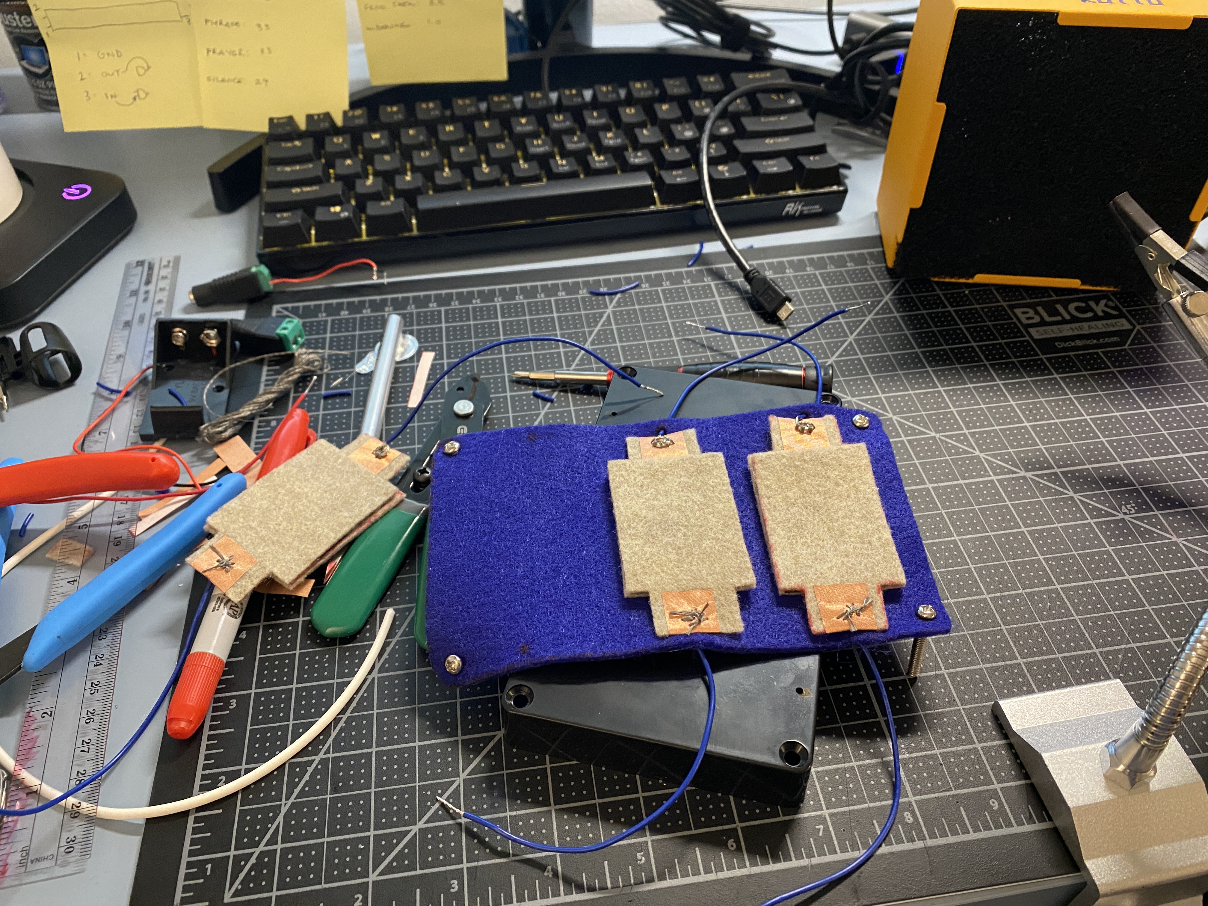
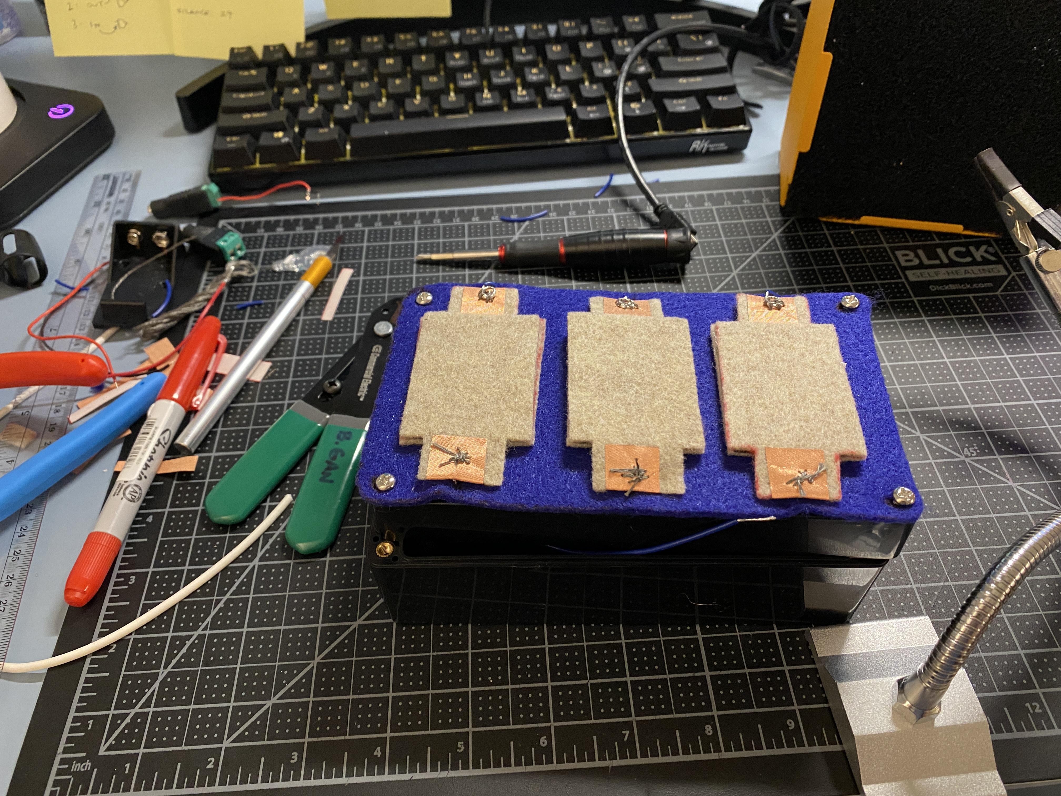
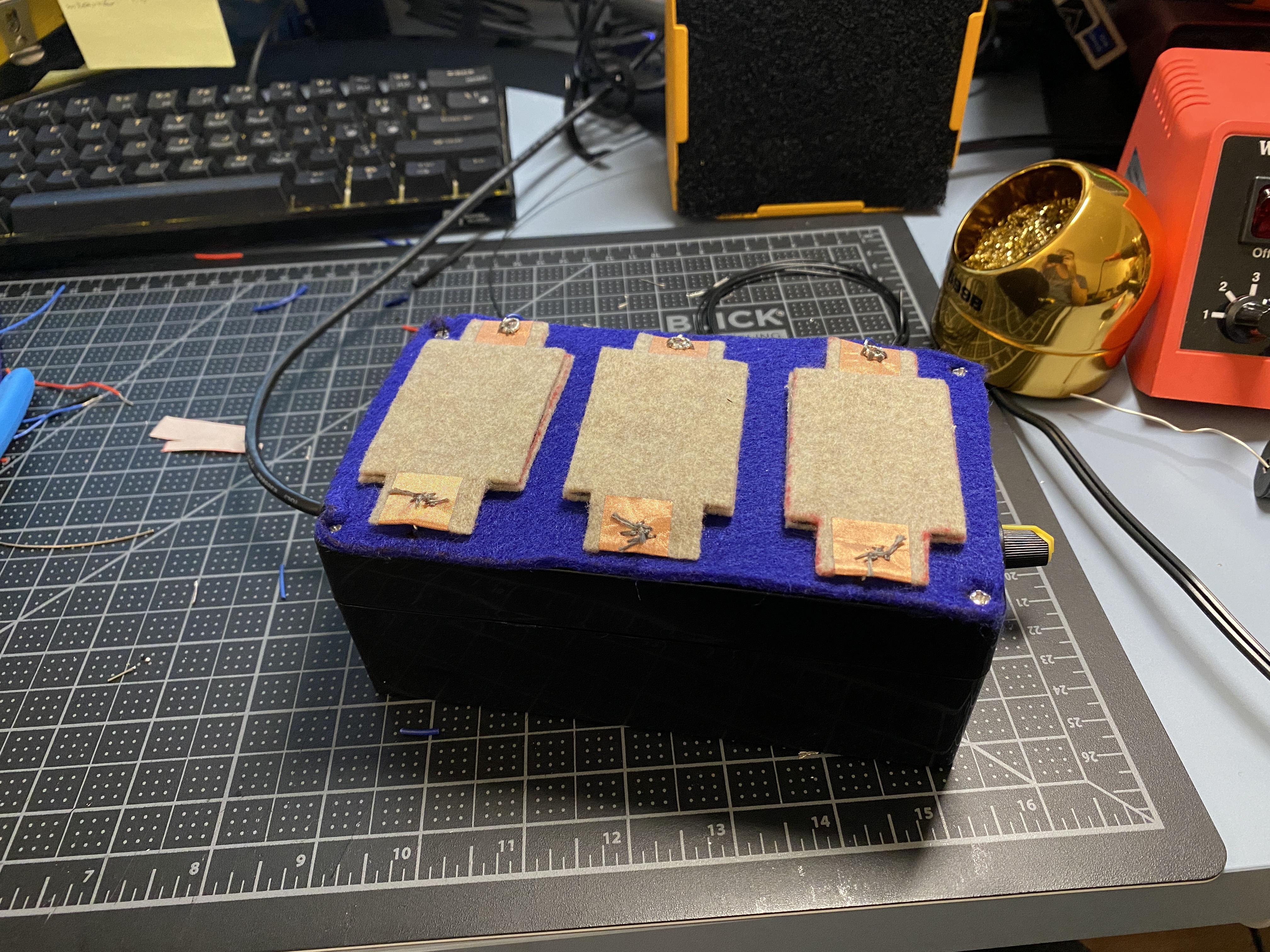
Next I worked on creating an enclosure, as well as recreating the textile
analog sensors. My initial idea was to have the three textile sensors on one
pad/piece of felt, with a top layer of felt, with each sensor separated by a
line of stitching. The process of housing it and solder the leads onto the PCB
took priority over adding the top layer, so as it is now the sensors are visible.
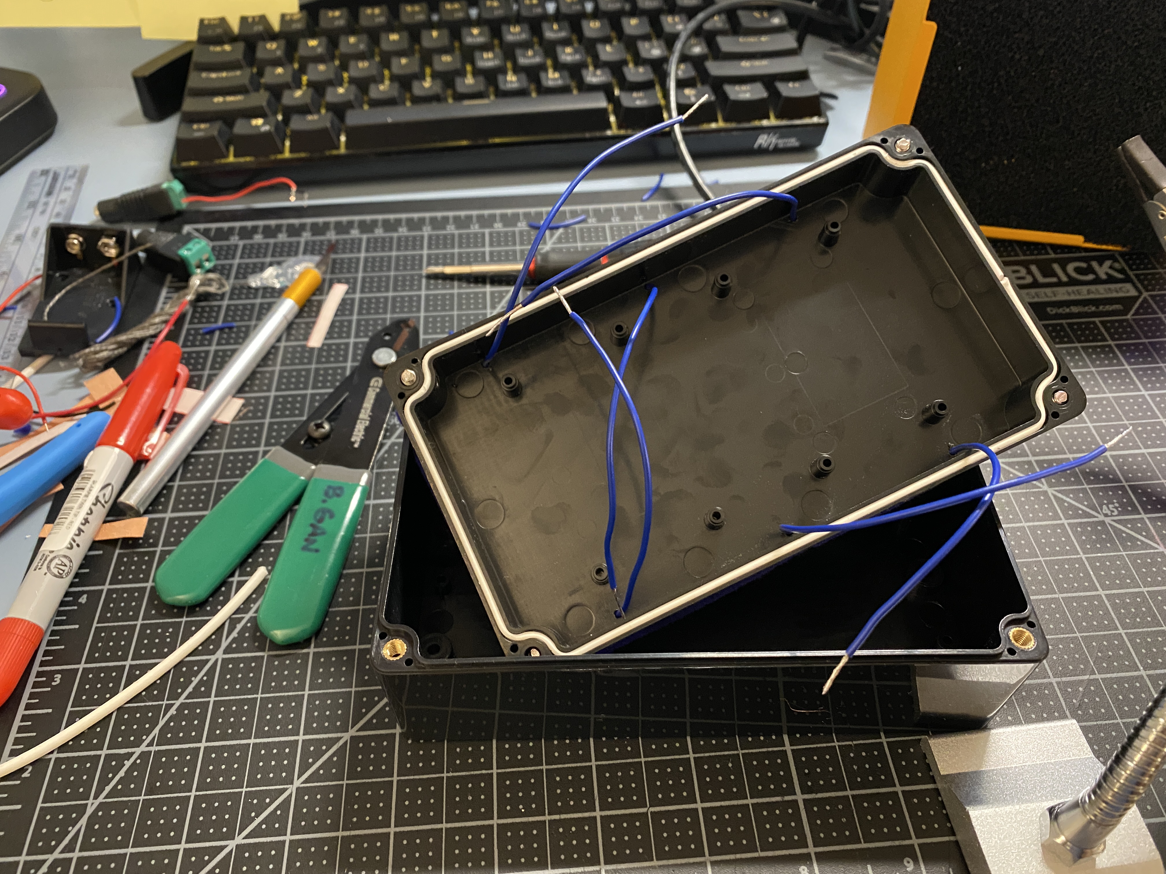
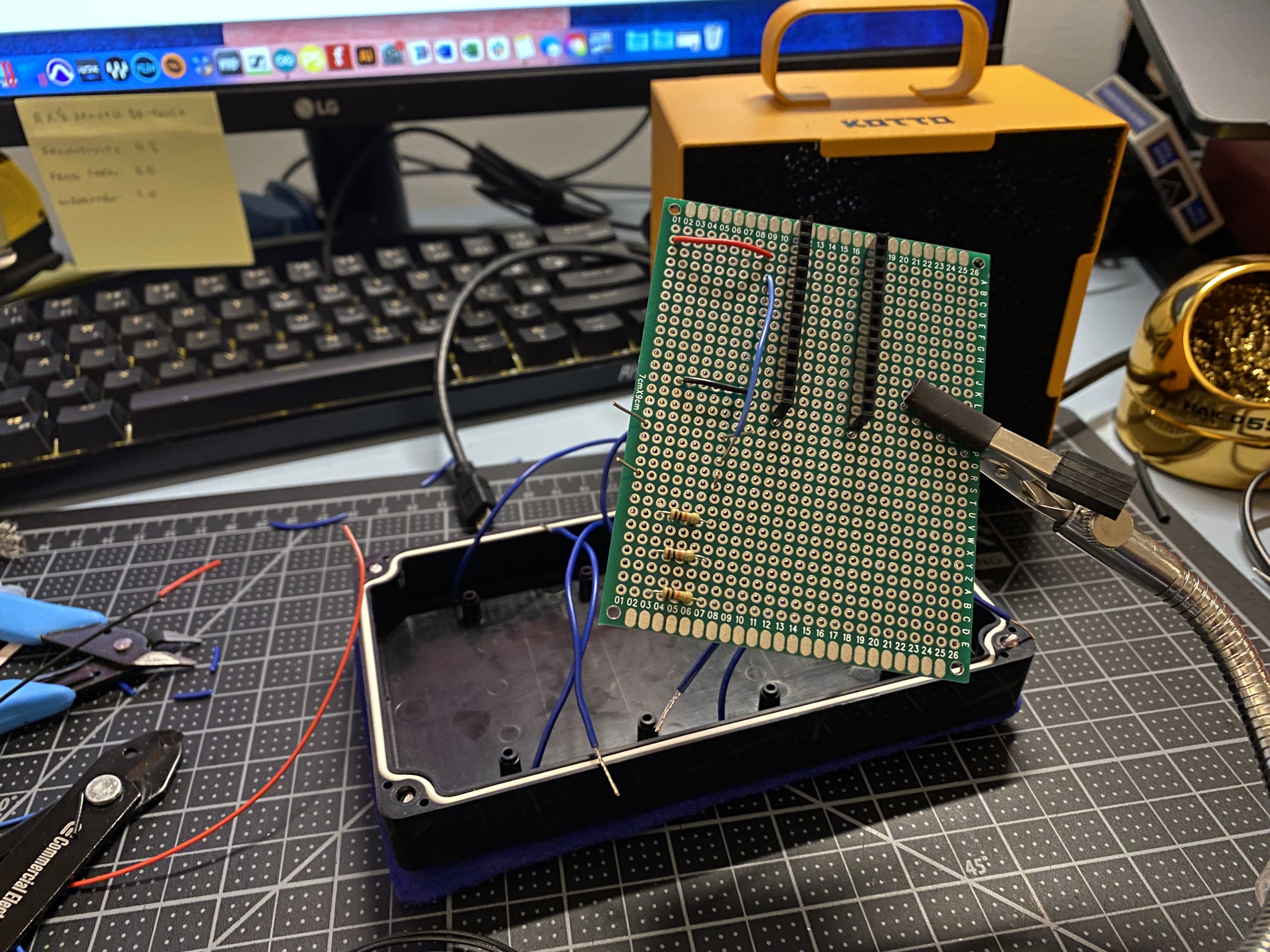
Instead of creating a cardboard proto enclosure like I have been doing in the
past, I purchased a plastic enclosure and drilled holes into it for the six leads
from the sensors, a potentiometer, and a micro USB port. I added the USB
port so that the Arduino connection can be made easily from outside of the
container.
I also adjusted the P5 sketch and created three arcs. With the four sensor
inputs, I used them across all three arcs to manipulate different elements of
the object.