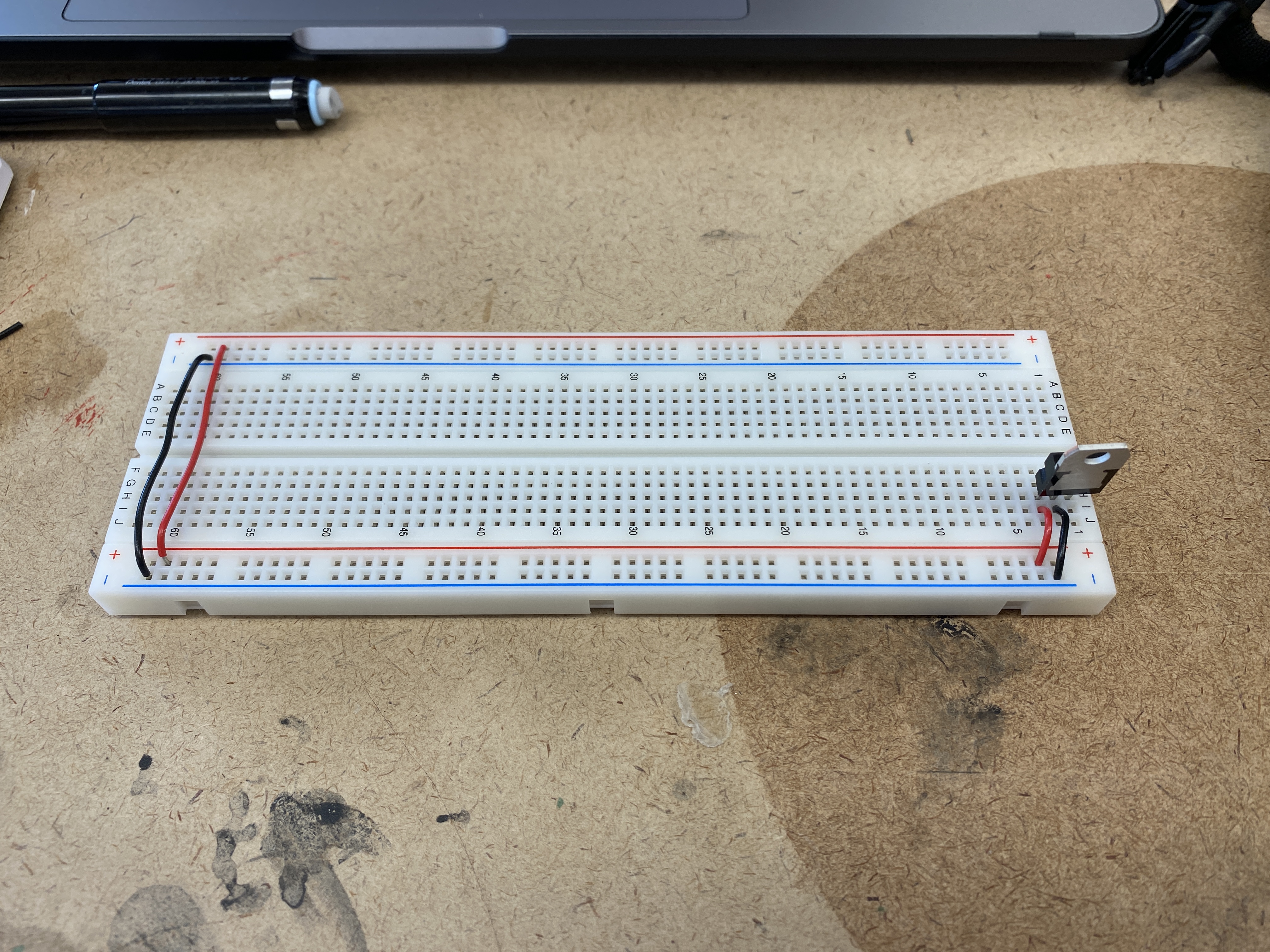
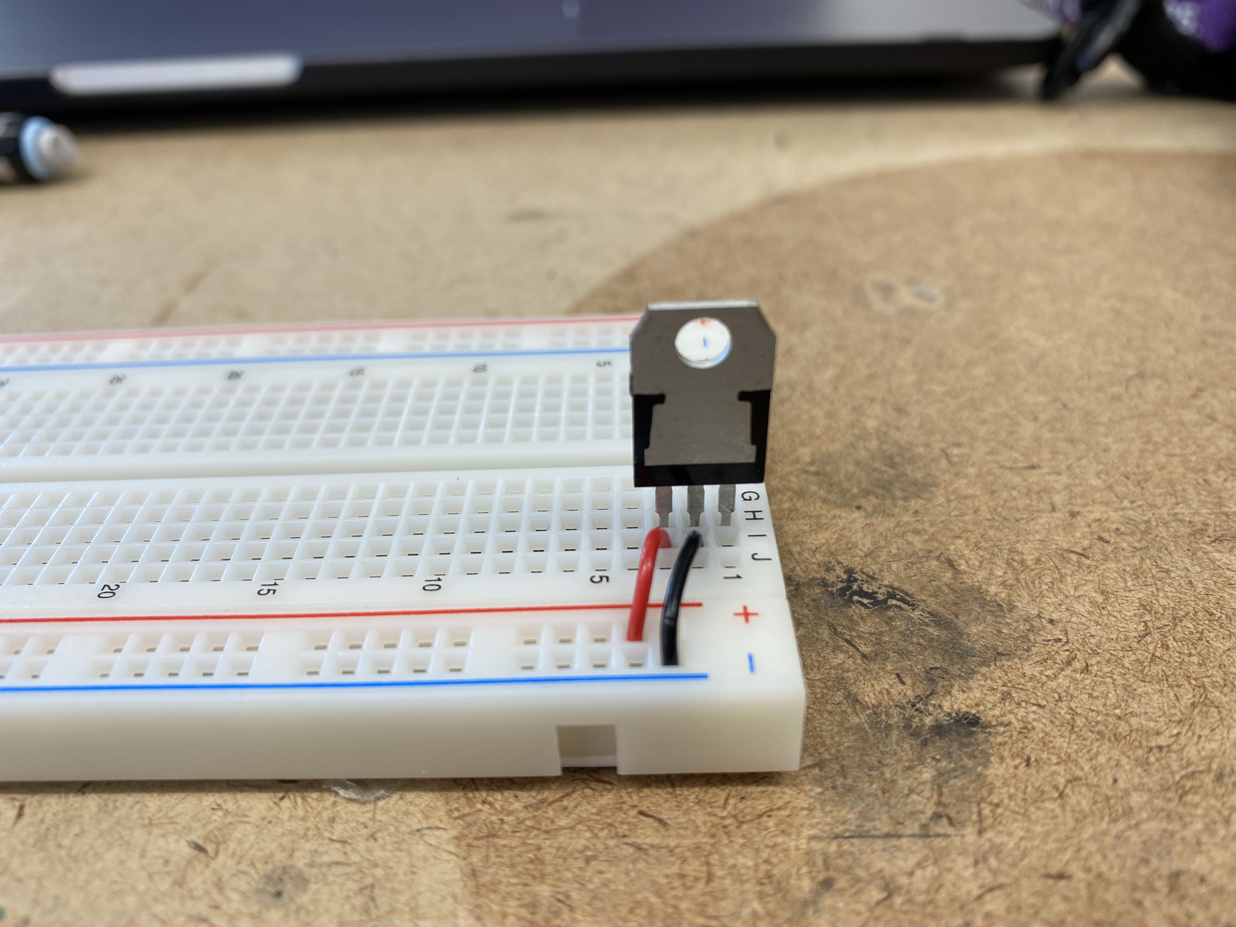
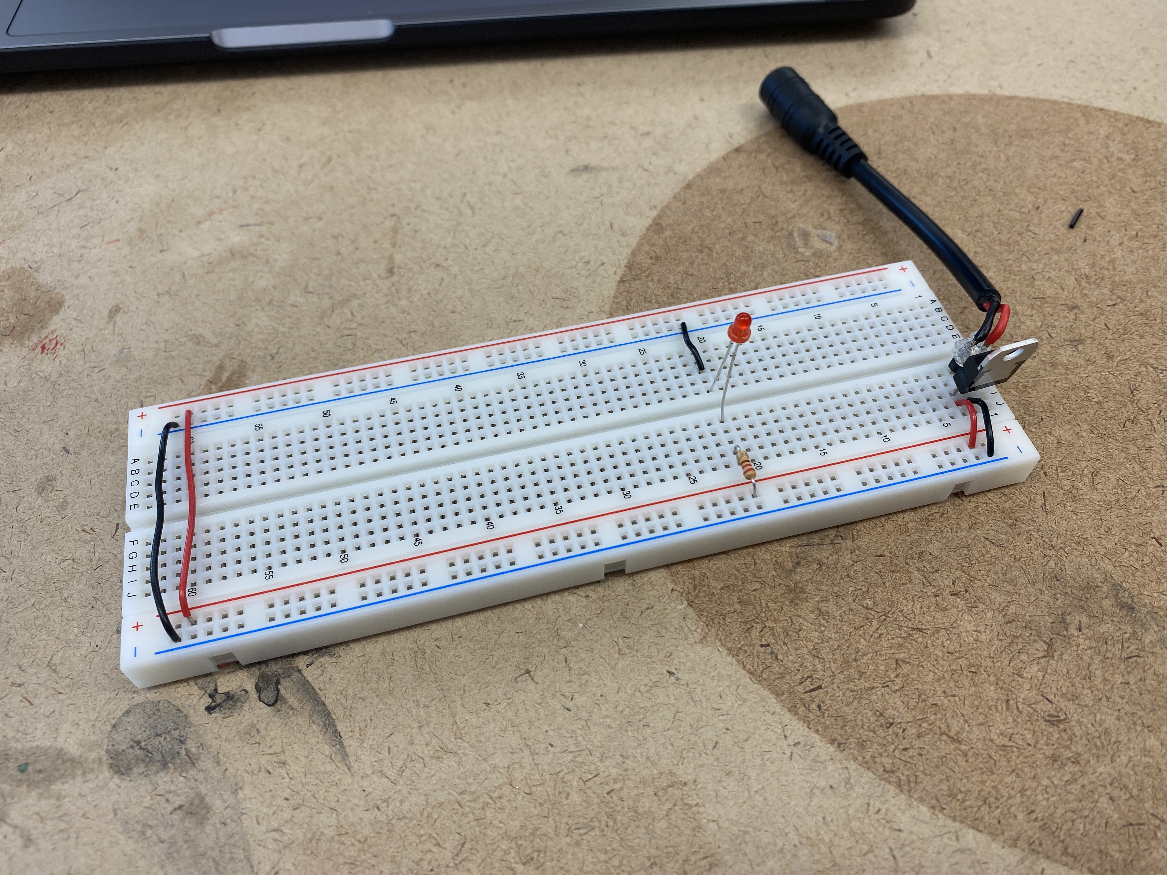
Setting up the breadboard - using a 7805 regulator, and connecting the ground and voltage
buses throughout the board and to the proper pins of the regulator.
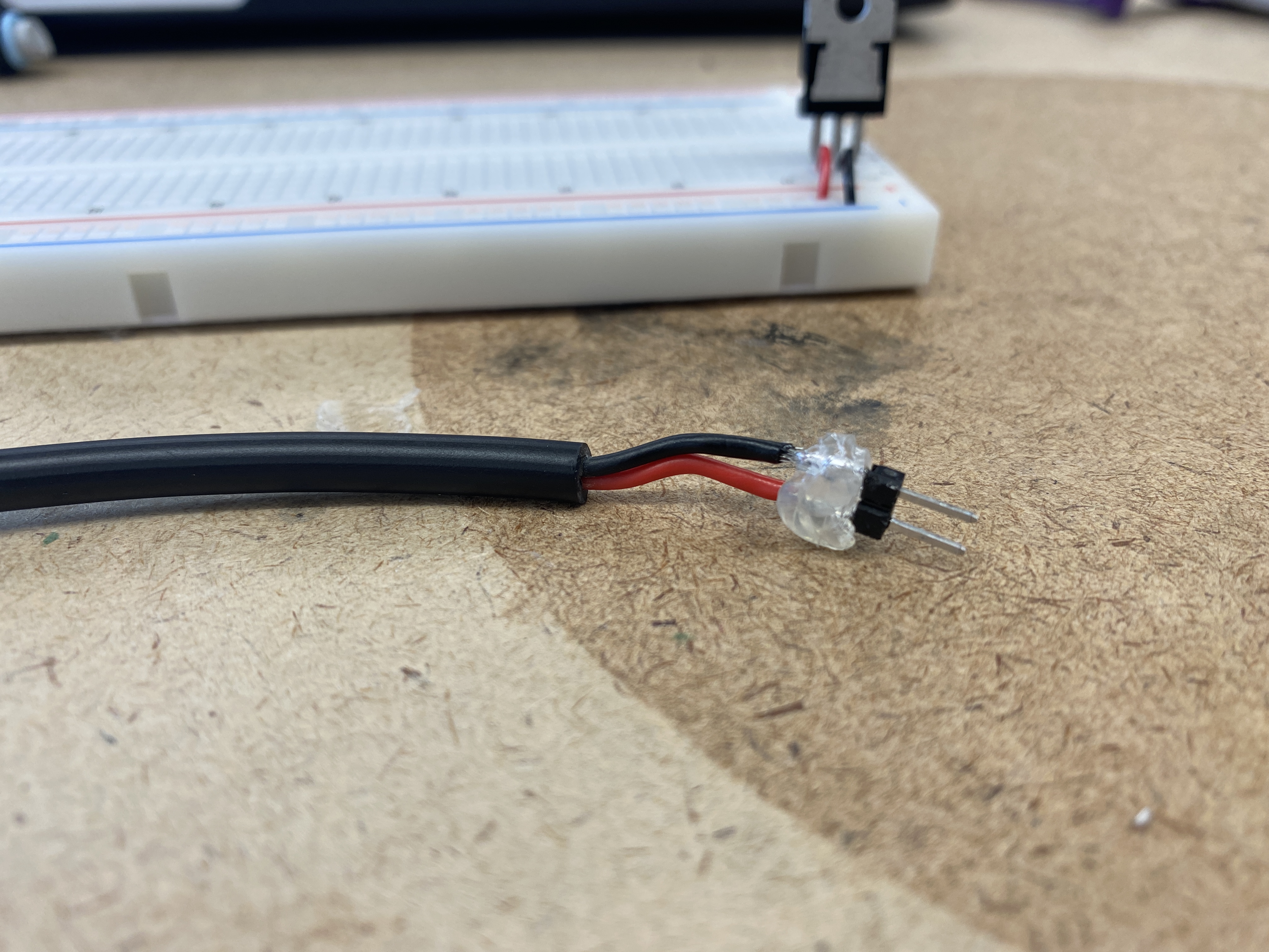
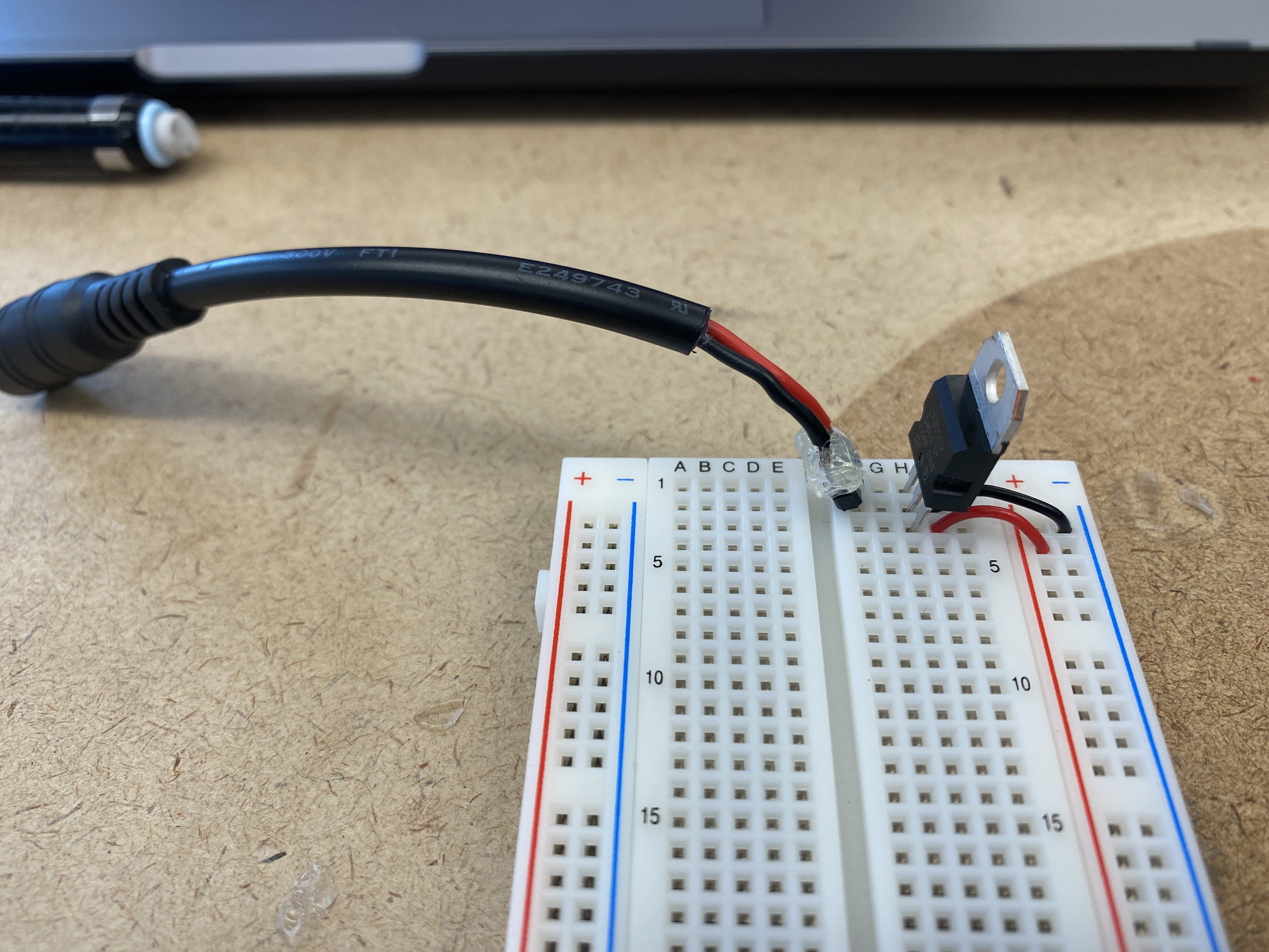
Soldered a DC power jack to two header pins and covered the connections in hot glue to prevent
any shorts. Connected the jack to the breadboard correlating to te correct ground and voltage in
pins of the regulator.
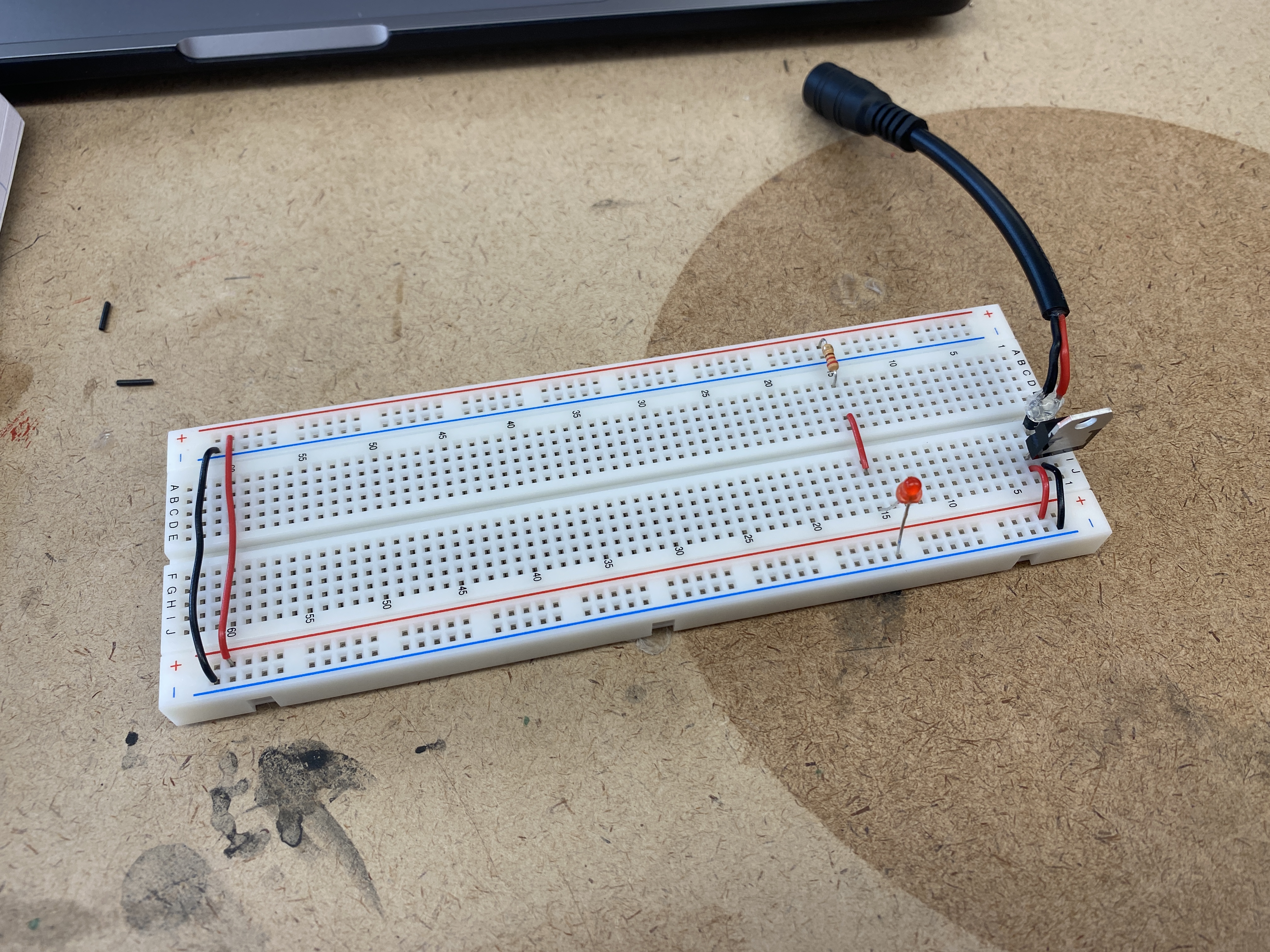
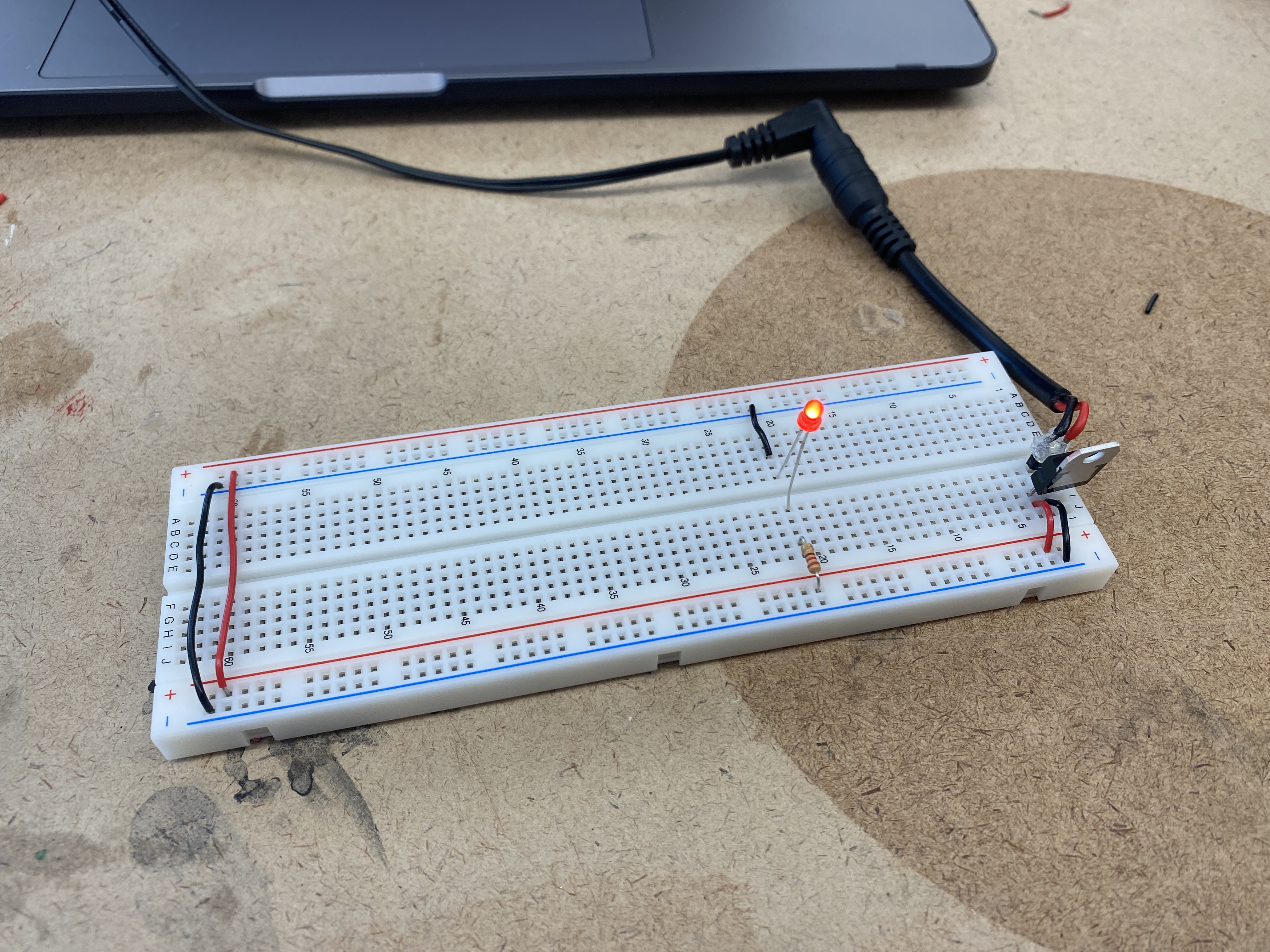
Will it light?
Test 01
Yes. The wiring is correct with the resistor in series between the voltage and LED.
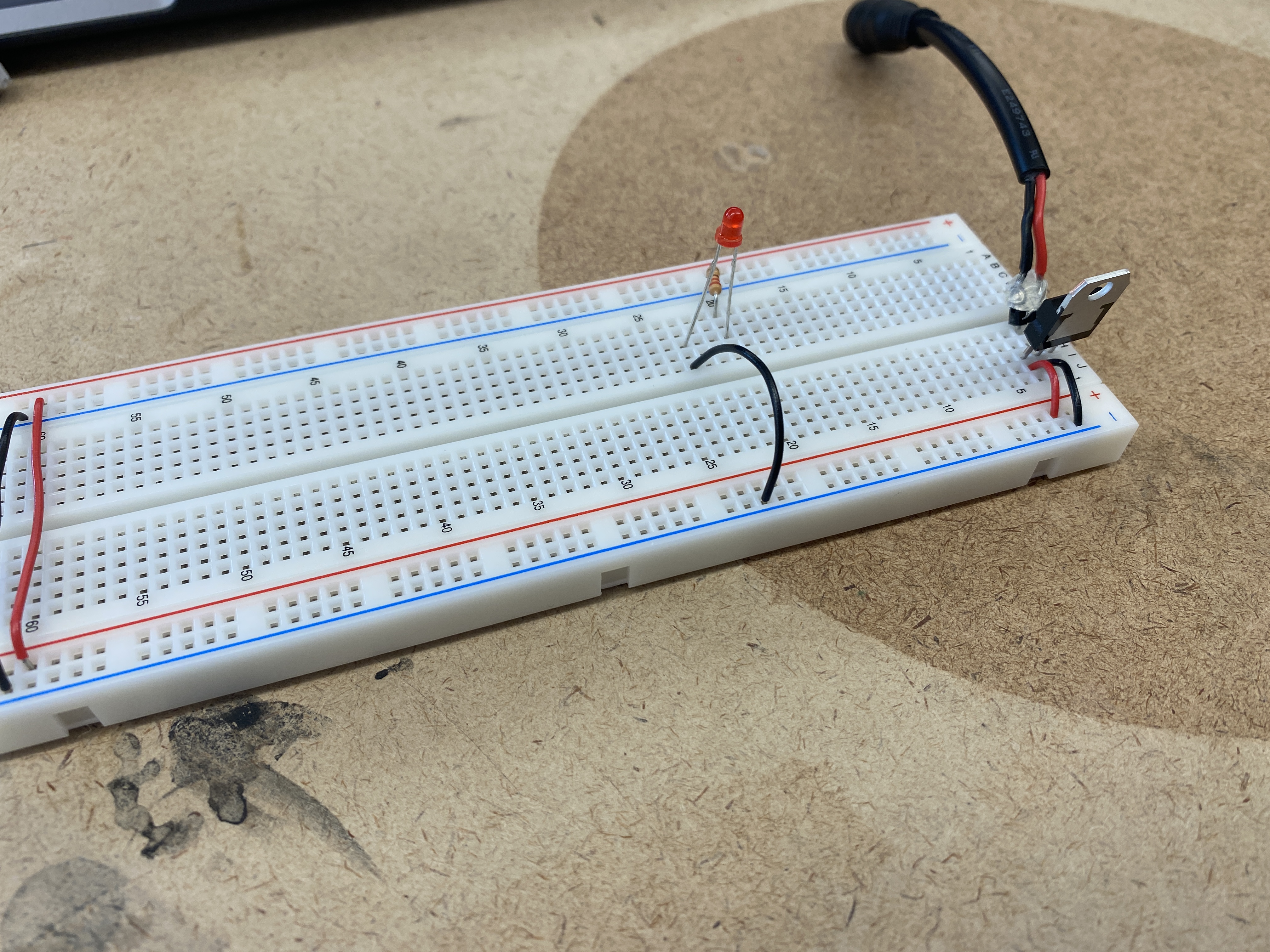
Test 02
No. The LED is connected to the ground bus but has no voltage going to the anode. The resistor
has one leg in the voltage bus and nothing on the other leg. Although the resistor and LED are in the same row,
the center divider breaks up the connection so we are left with an incomplete circuit.
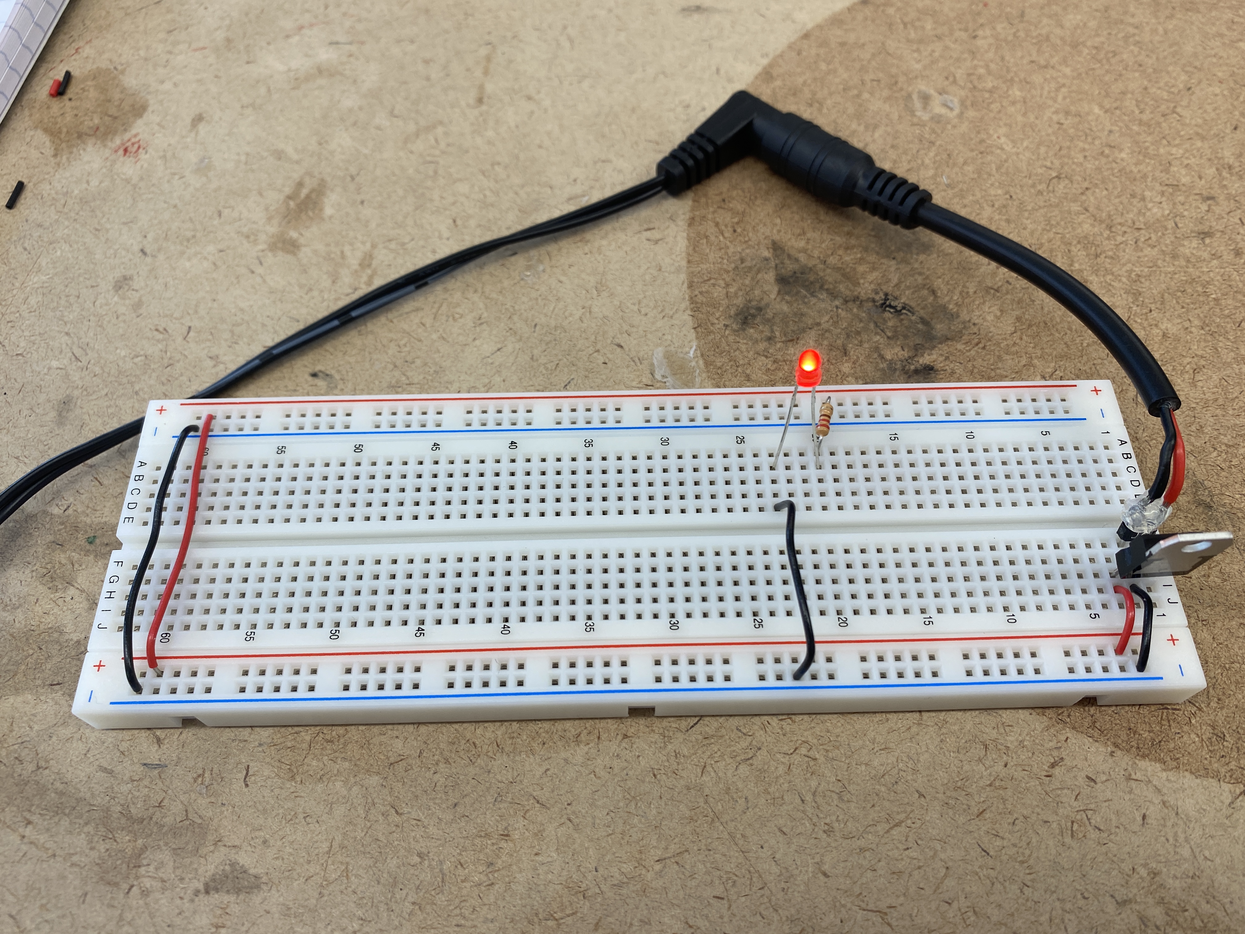
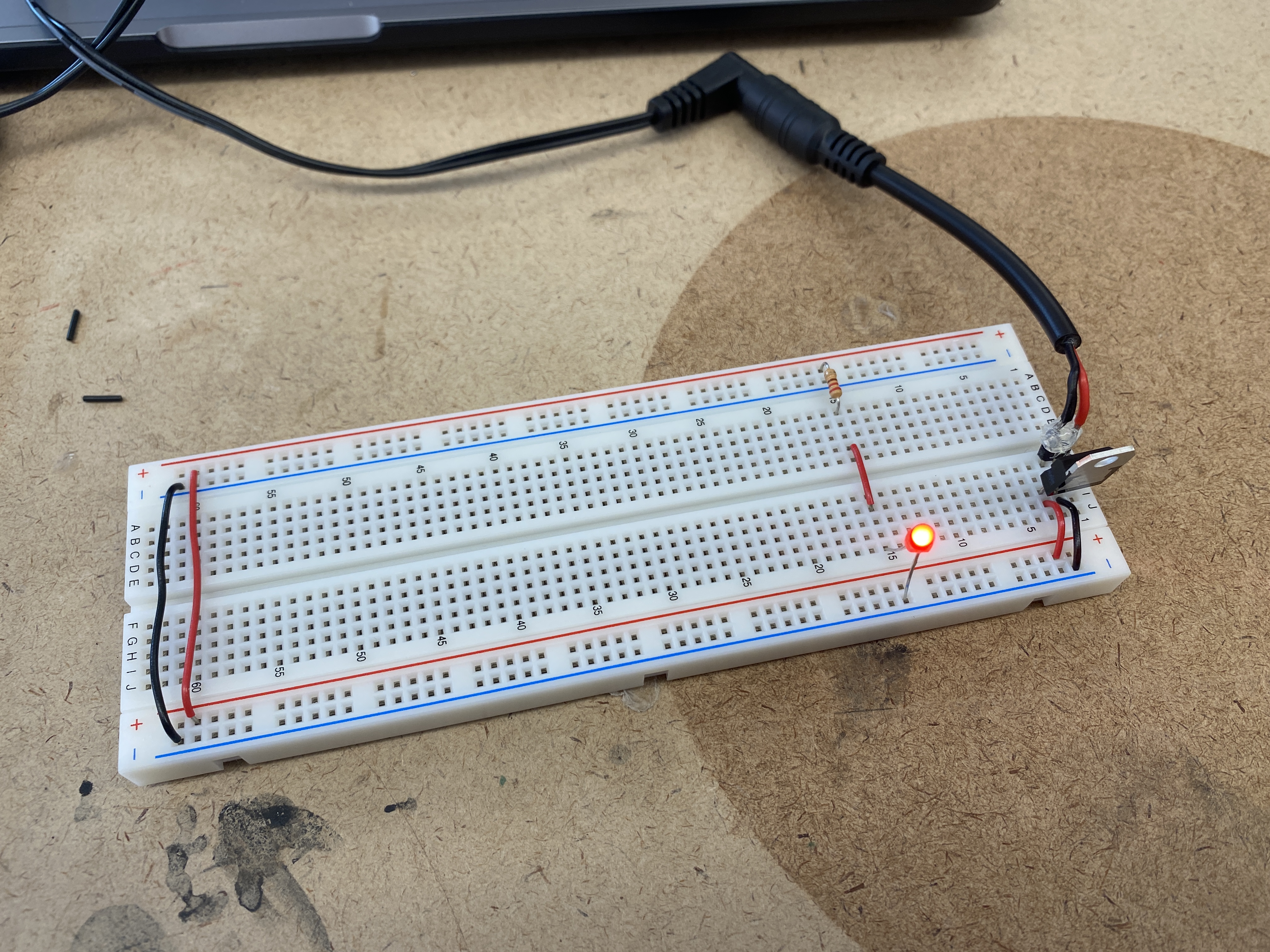
Test 03
Yes. It is essentially the same schemiatic as the first circuit, aside from the physical placements
of the components on the breadboard. The components are in the same locations on the breadboard as test 2,
however this circuit works due to the hookup wire bridging the two sides and connecting the resistor to the LED.
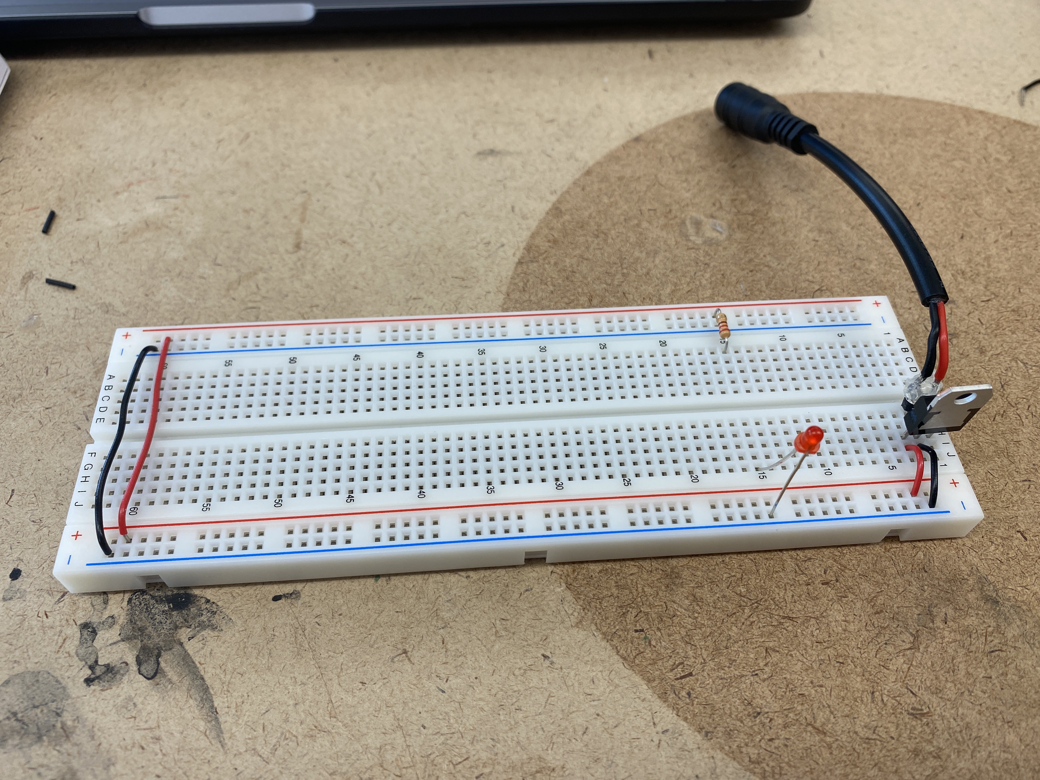
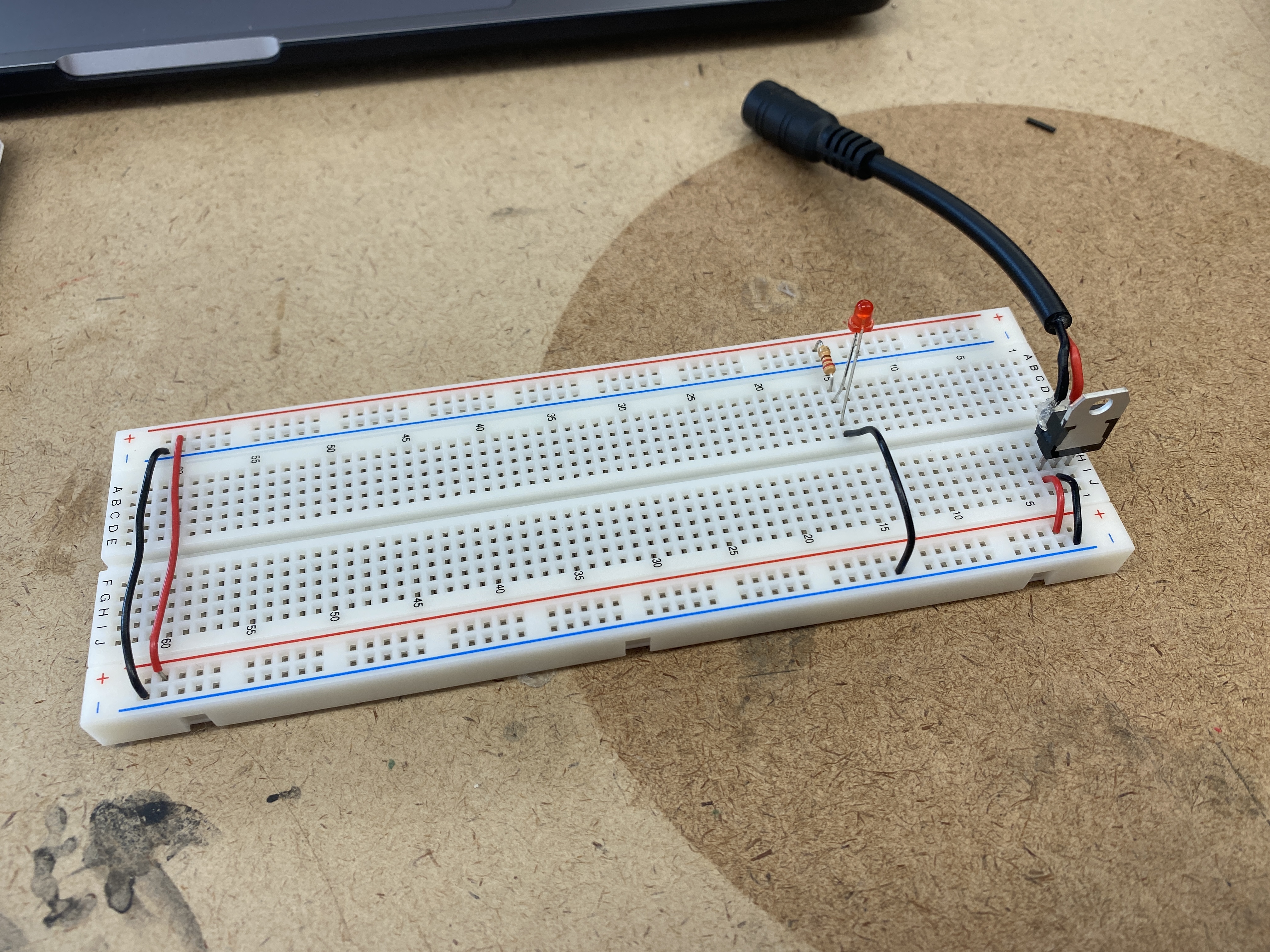
Test 04
No. The resistor and the LED are all connected in the same row, with the wire jumping to the ground bus.
This is causing a short circuit.
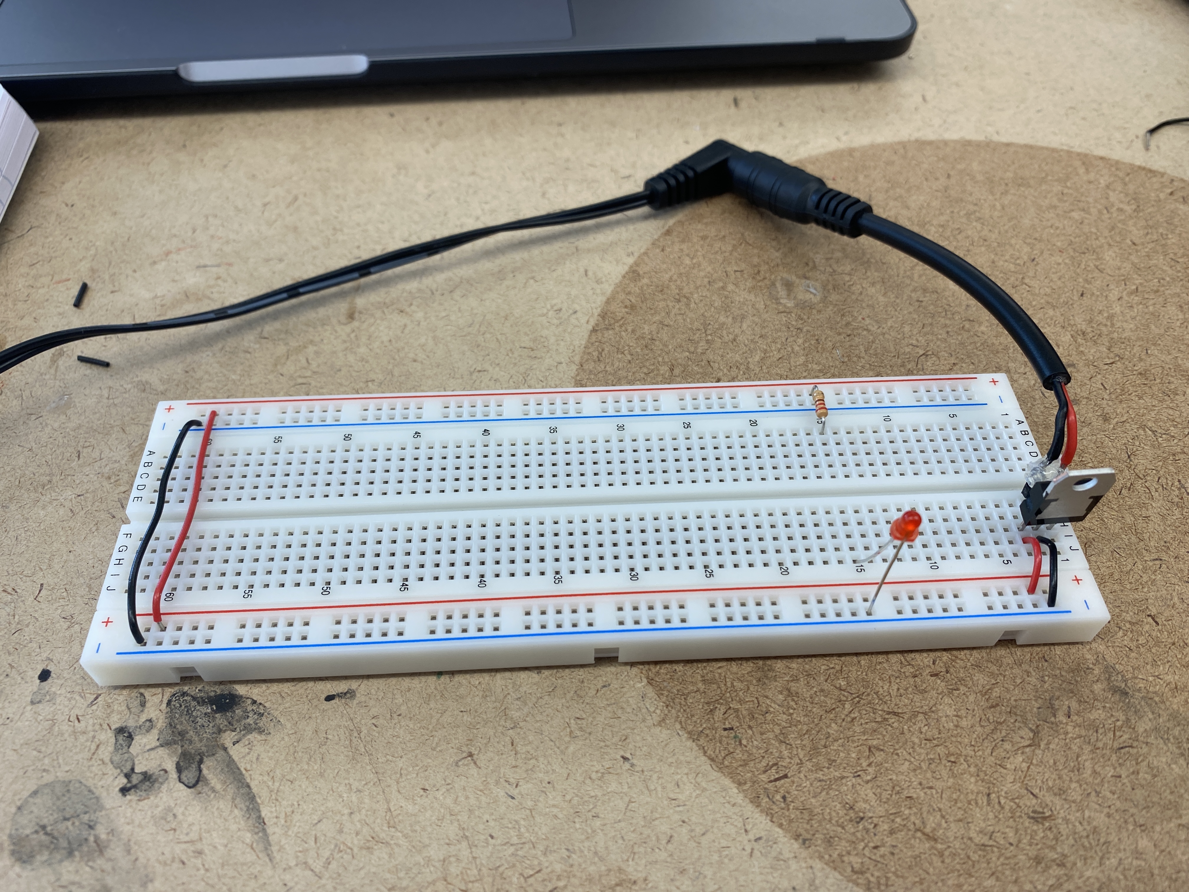
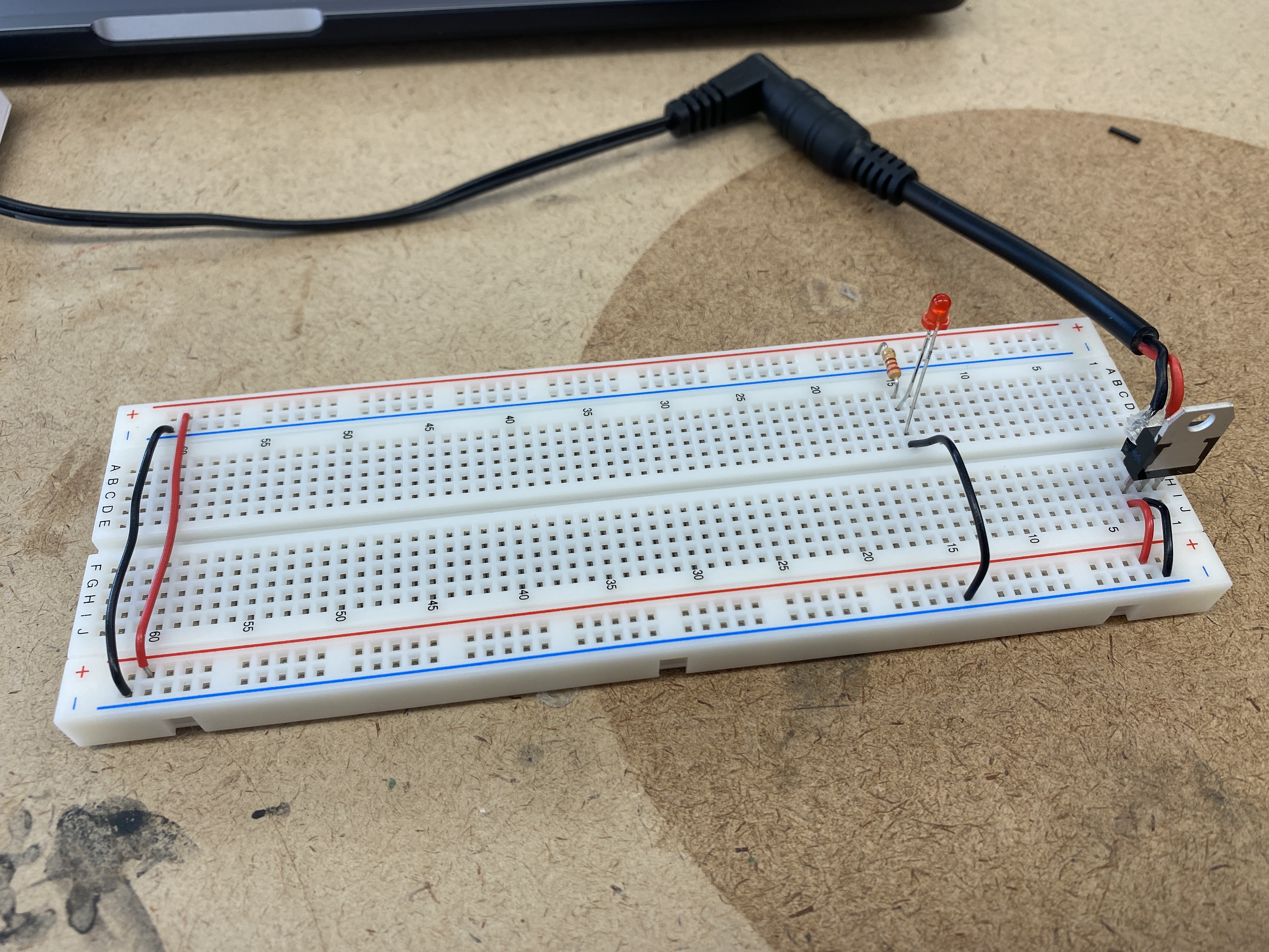
Test 04
Yes. The LED is bridging the gap to have a connection to both the ground bus and the resistor.
Electronics
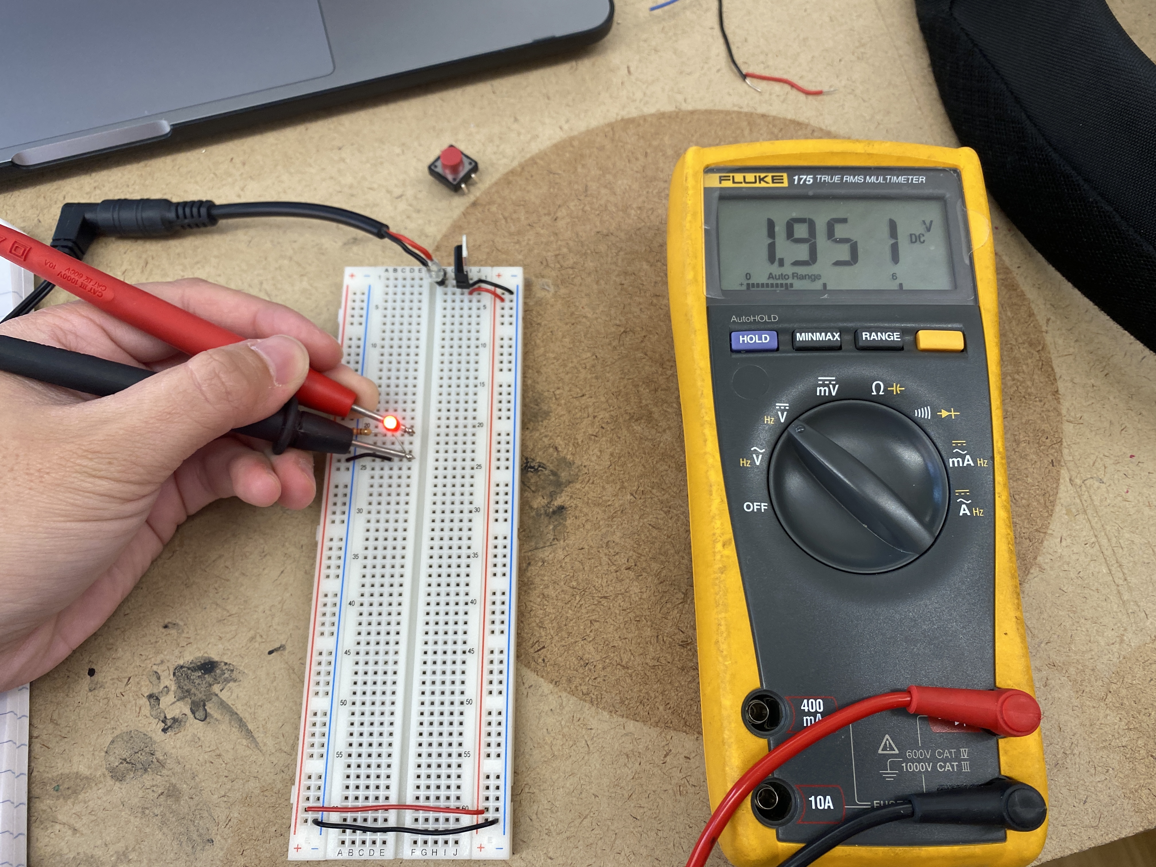
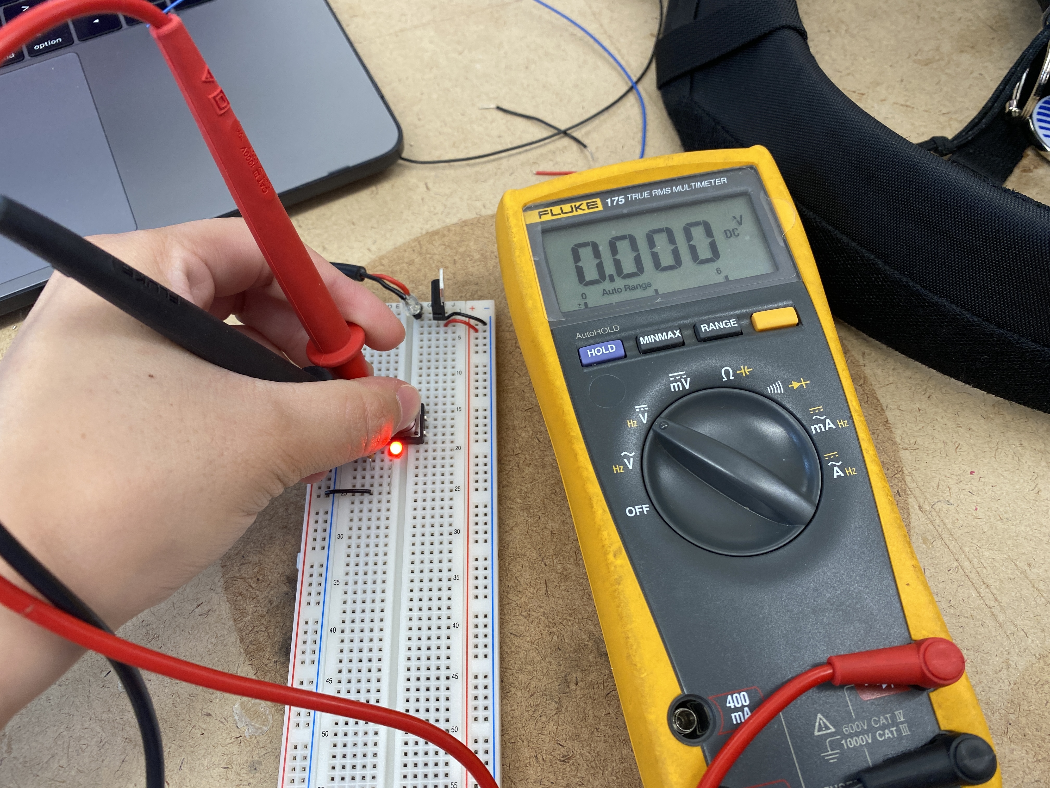
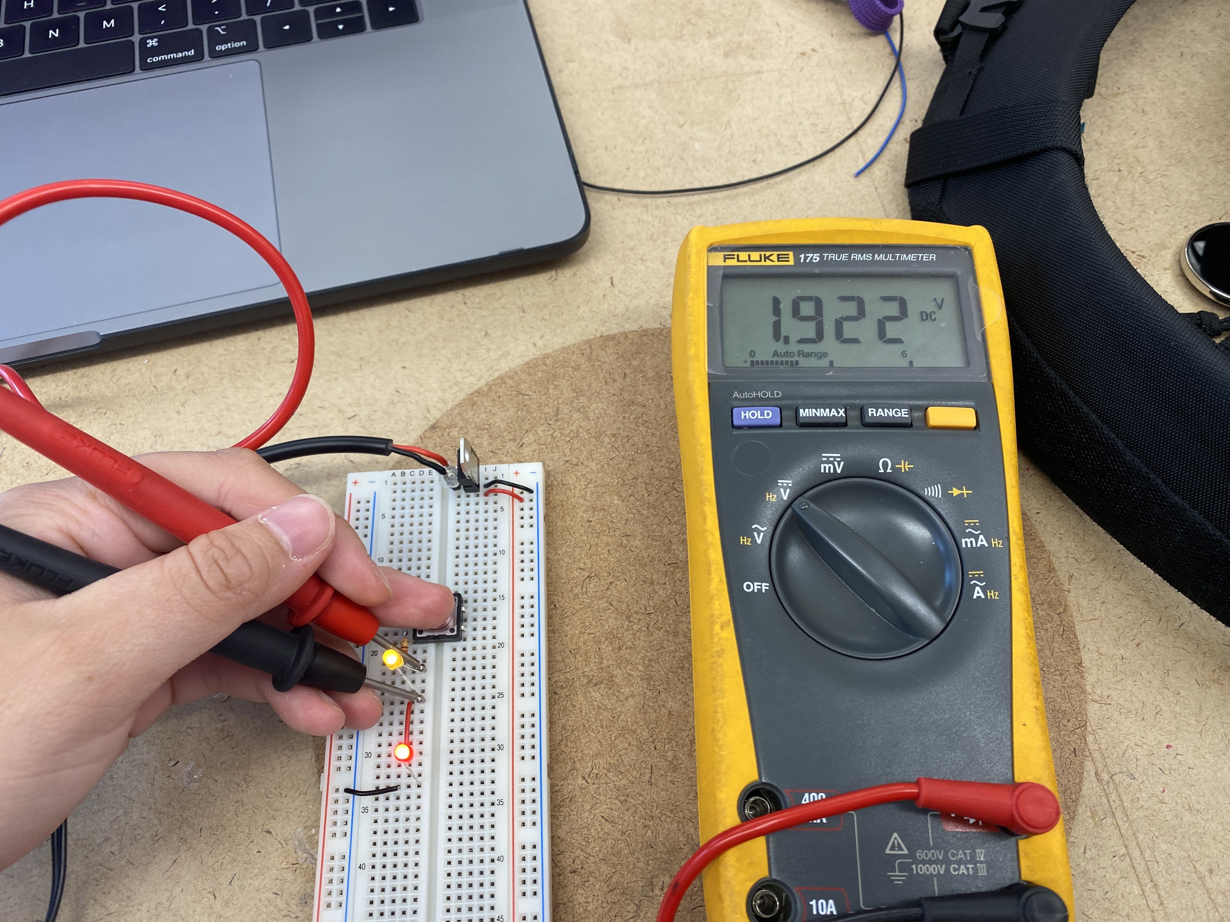
Measuring the voltage drop across the LED.
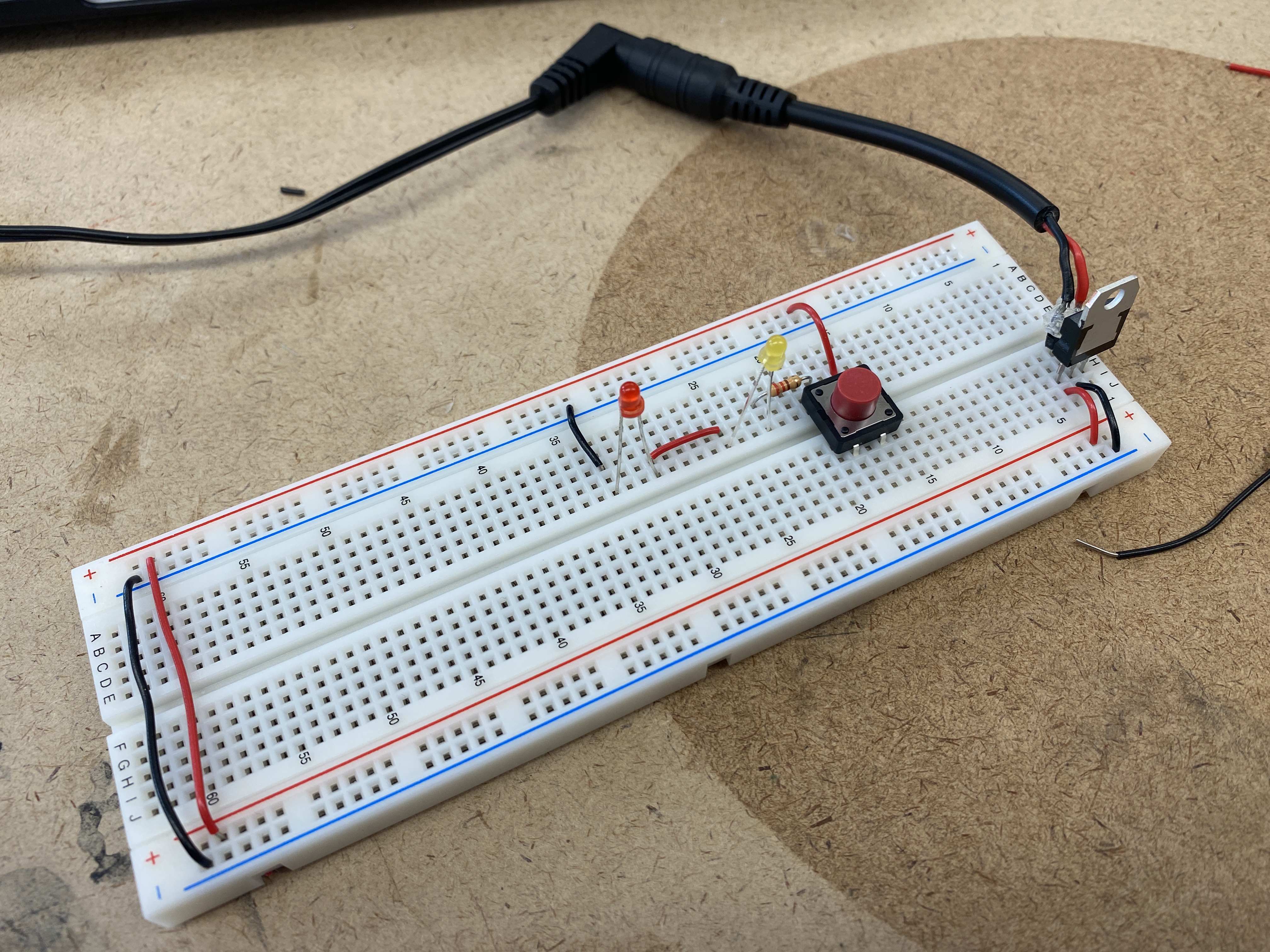
Switched LED circuit with a pushbutton
Measuring the voltage across the pushbutton
On the left, the multimeter reads around 5V because the voltage is stopping here, and not going
through the circuit to power the LED.
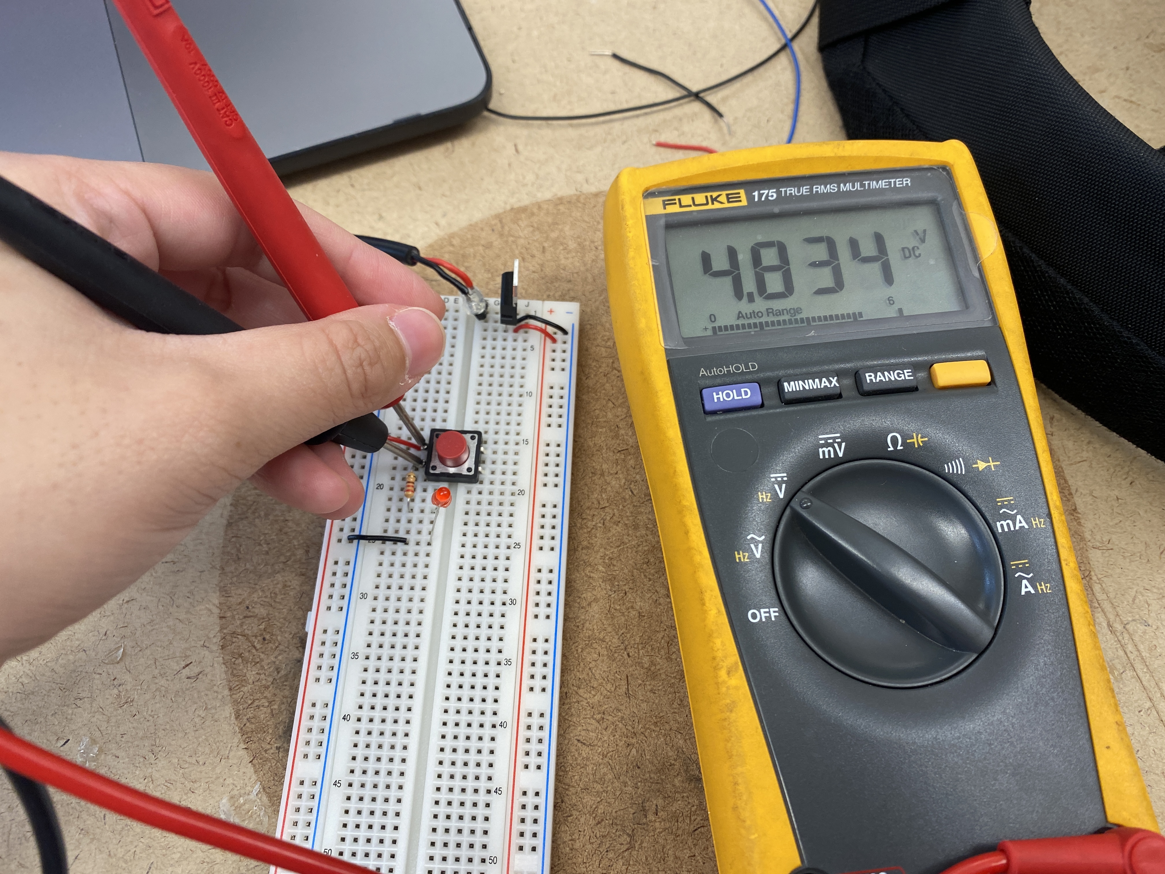
However, on the right the multimeter reads 0V, and this is because when the button is pushed,
the voltage is traveling through to power the LED.
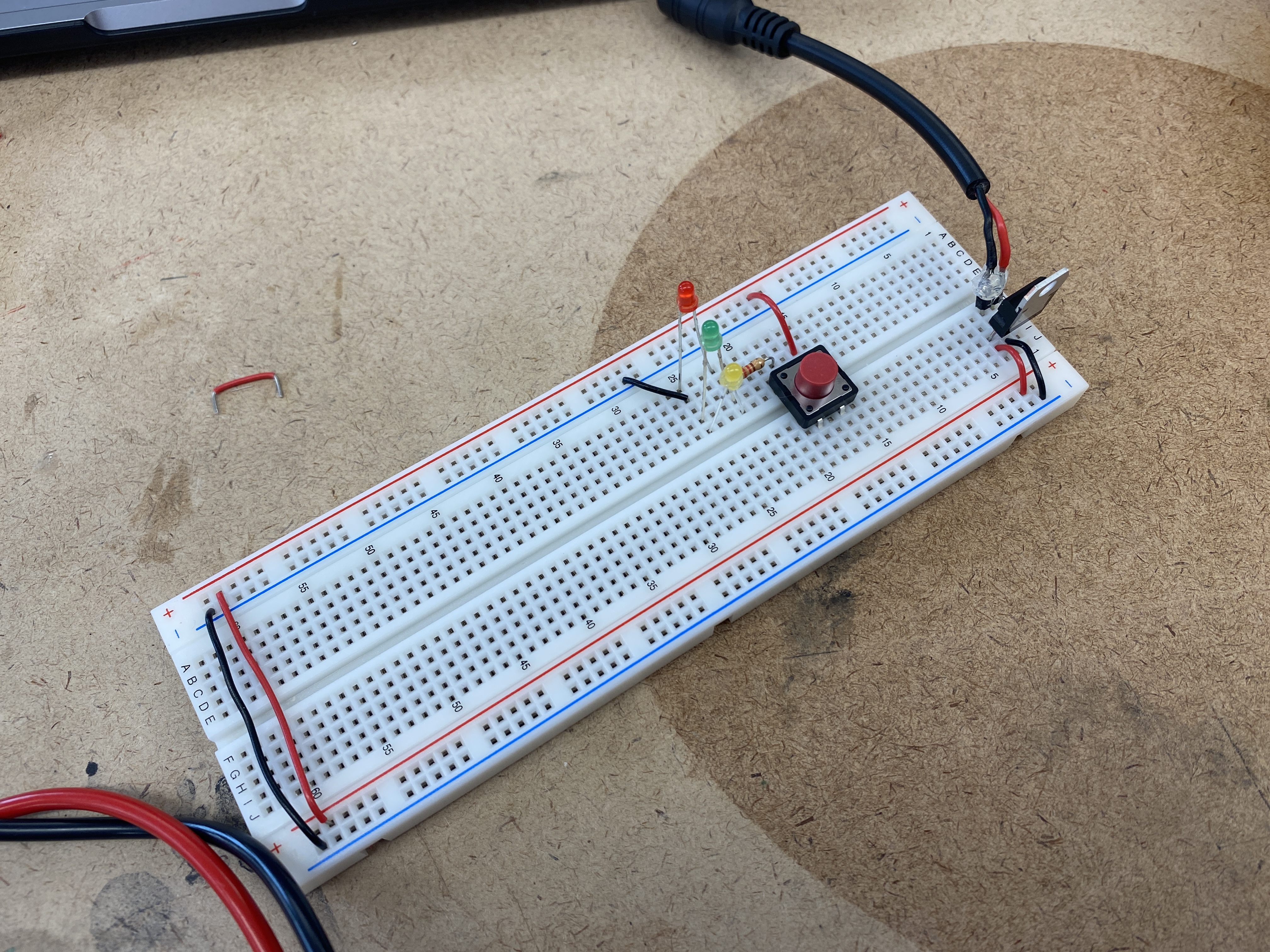
Components in series
Adding up voltage, and adding a third LED
After adding the third LED, none of the LEDs will light up because each one draws about 2V,
and the 5V powering the circuit is insufficient.
Components in parallel
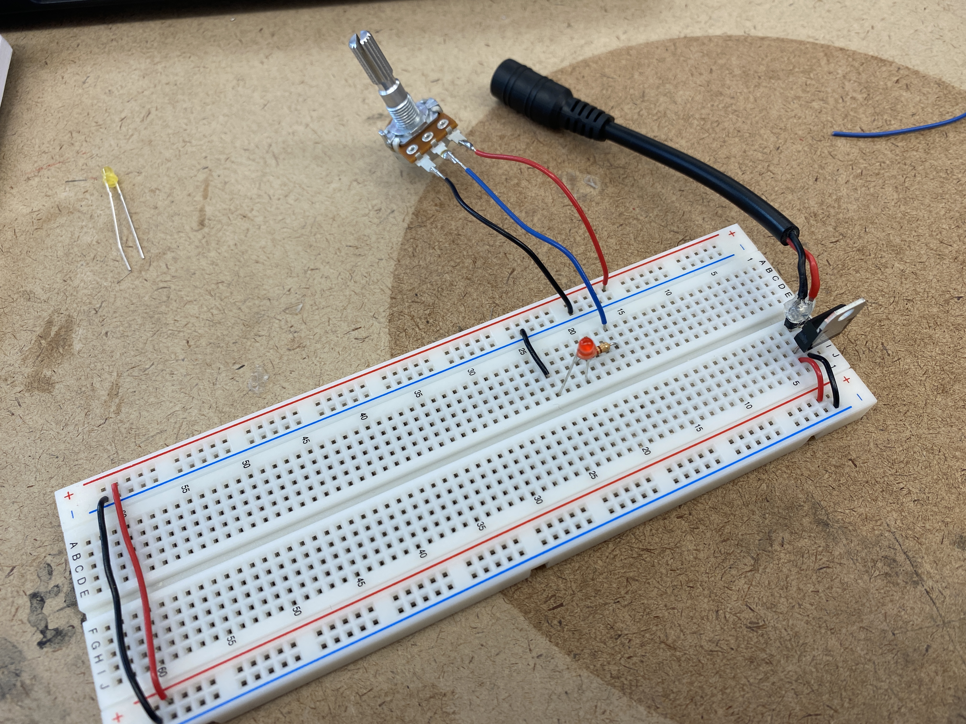
Generating a variable voltage with a potentiometer
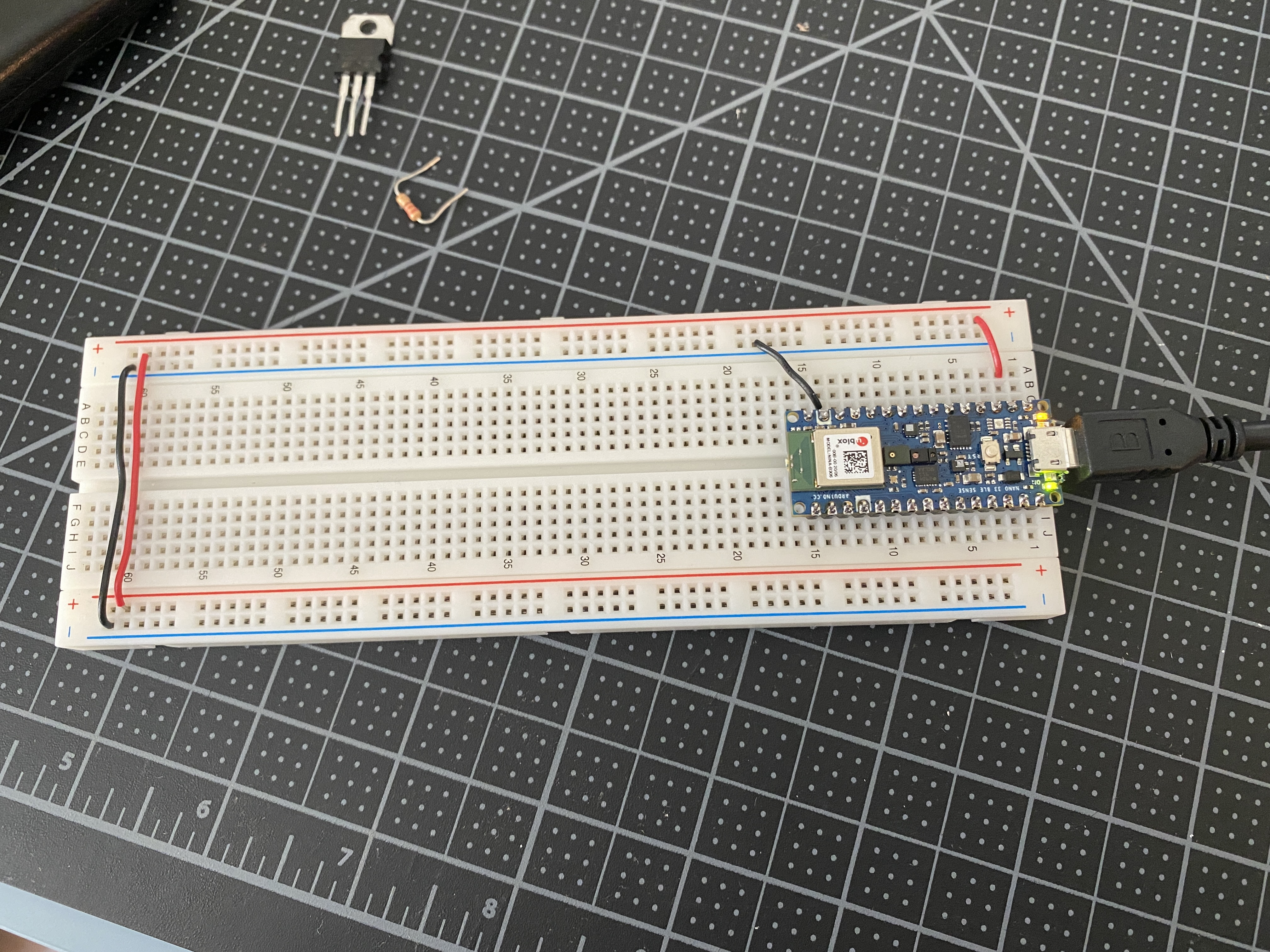
Using a breadboard with a microcontroller
With the Arduino Nano, I patched a wire from the pin 2 of the microcontroller
to the voltage bus which provides 3.3V to the breadboard, along with a wire connecting pin 14
of the microcontroller to the ground bus.
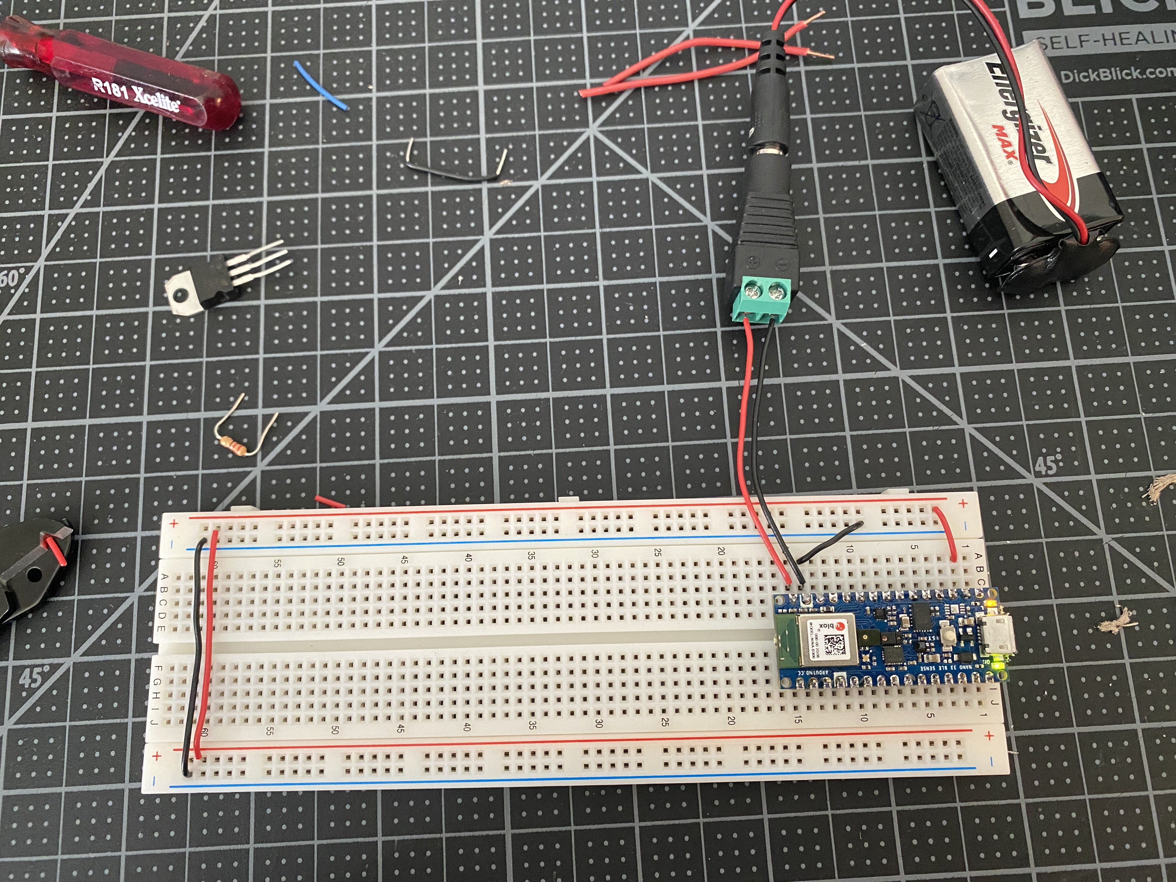
Powering a breadboard with a microcontroller via DC power supply
In order to power the breadboard via the microcontroller without a USB, I connected a DC power jack
to pins 14 and 15 of the Arduino (ground and voltage in) and added a 9V battery in line.
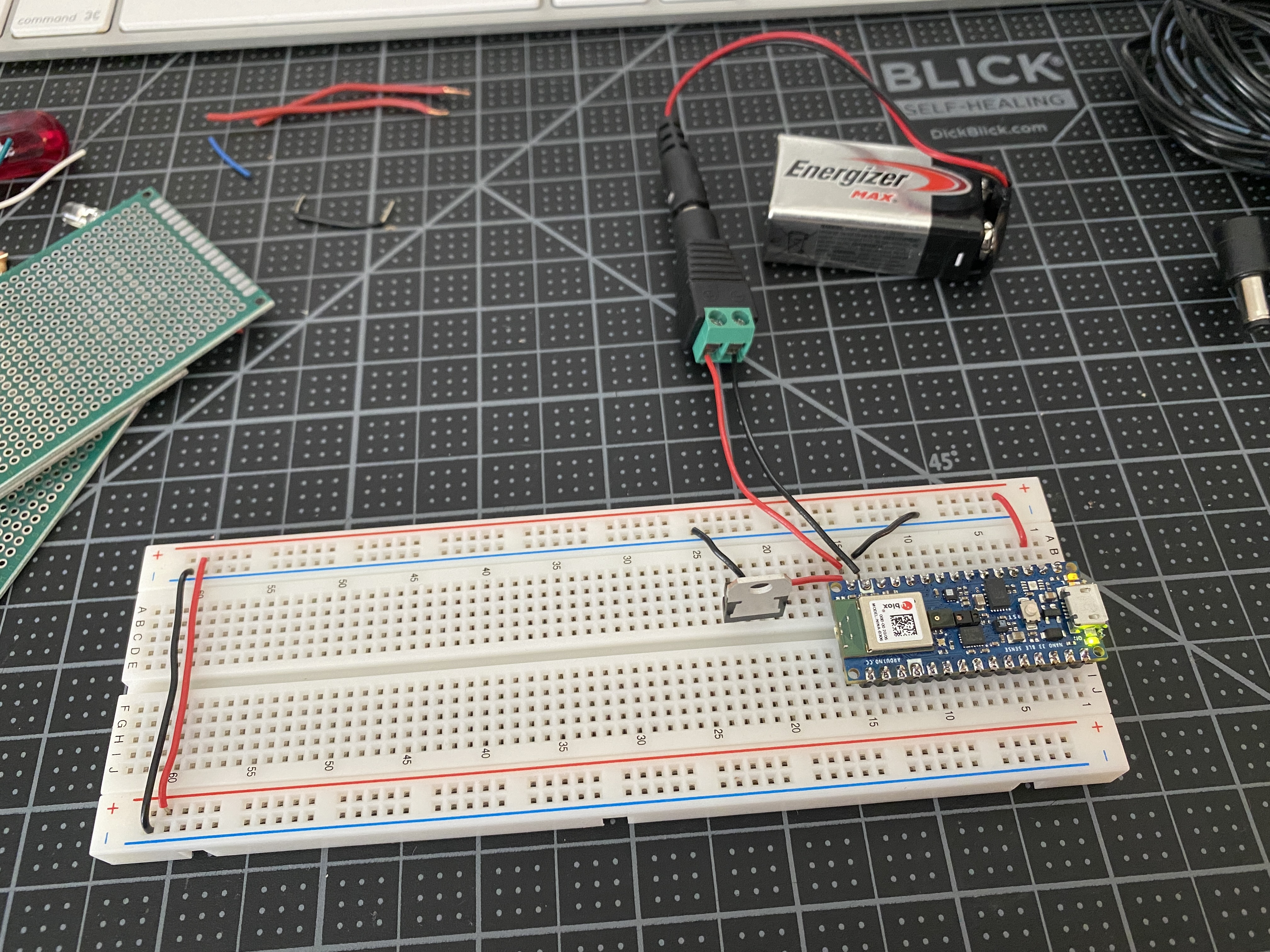
In this next test, I added a 5V regulator connected to pin 15 (voltage in) of the microcontroller,
in order to provide 5V to components who may require it, while the Arduino is still powering a 3.3V throughout
the breadboard's voltage bus. I did a test adding a switch and an LED off of the 5V regulator.
Switches and Pushbuttons
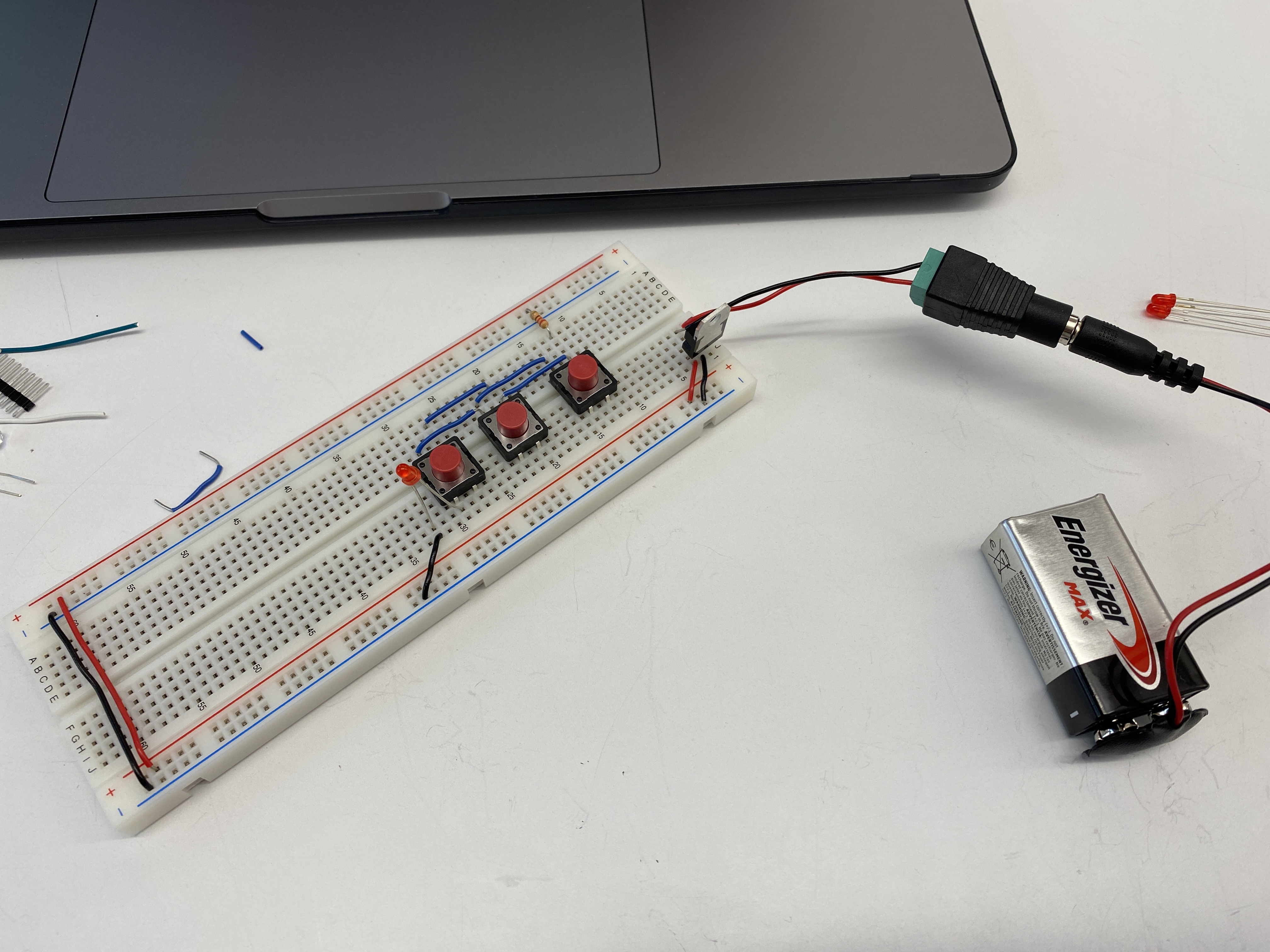
Project 1: Three Switches in Parallel
With the three switches in parallel, any one of the buttons will light up the LED.
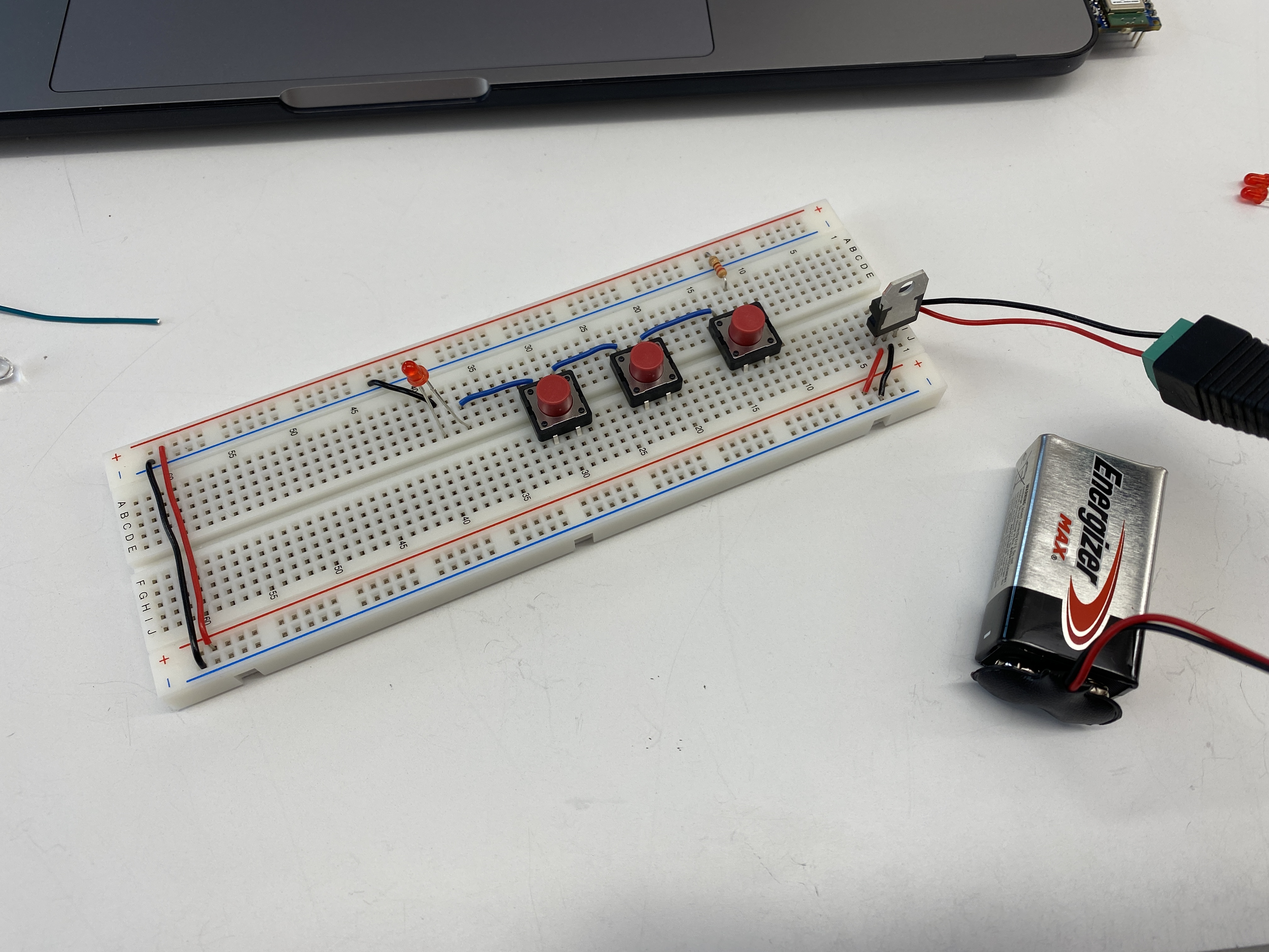
Project 2: Three Switches in Series
With three switches in series, all three must be pressed in order for the LED to light up.
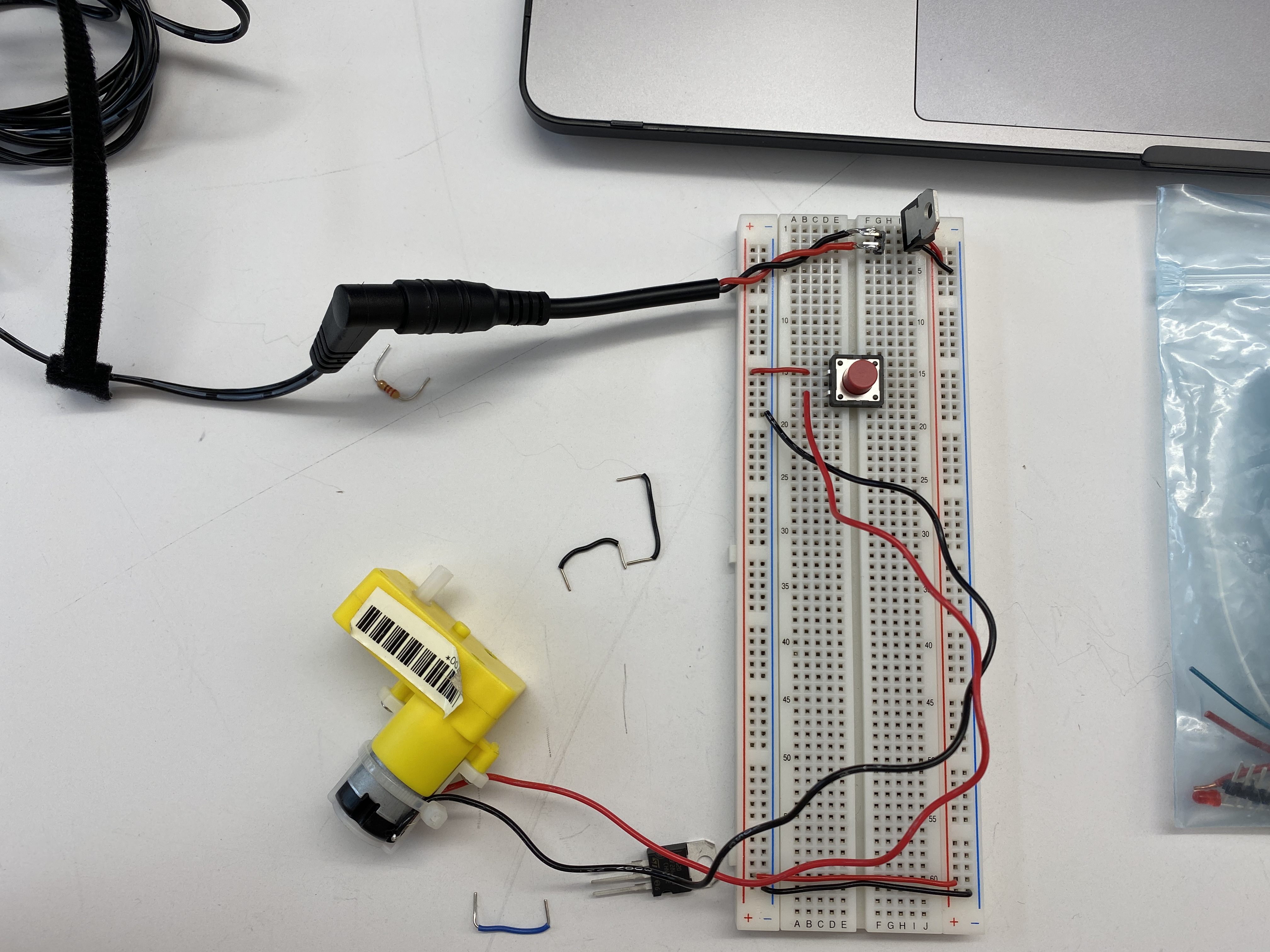
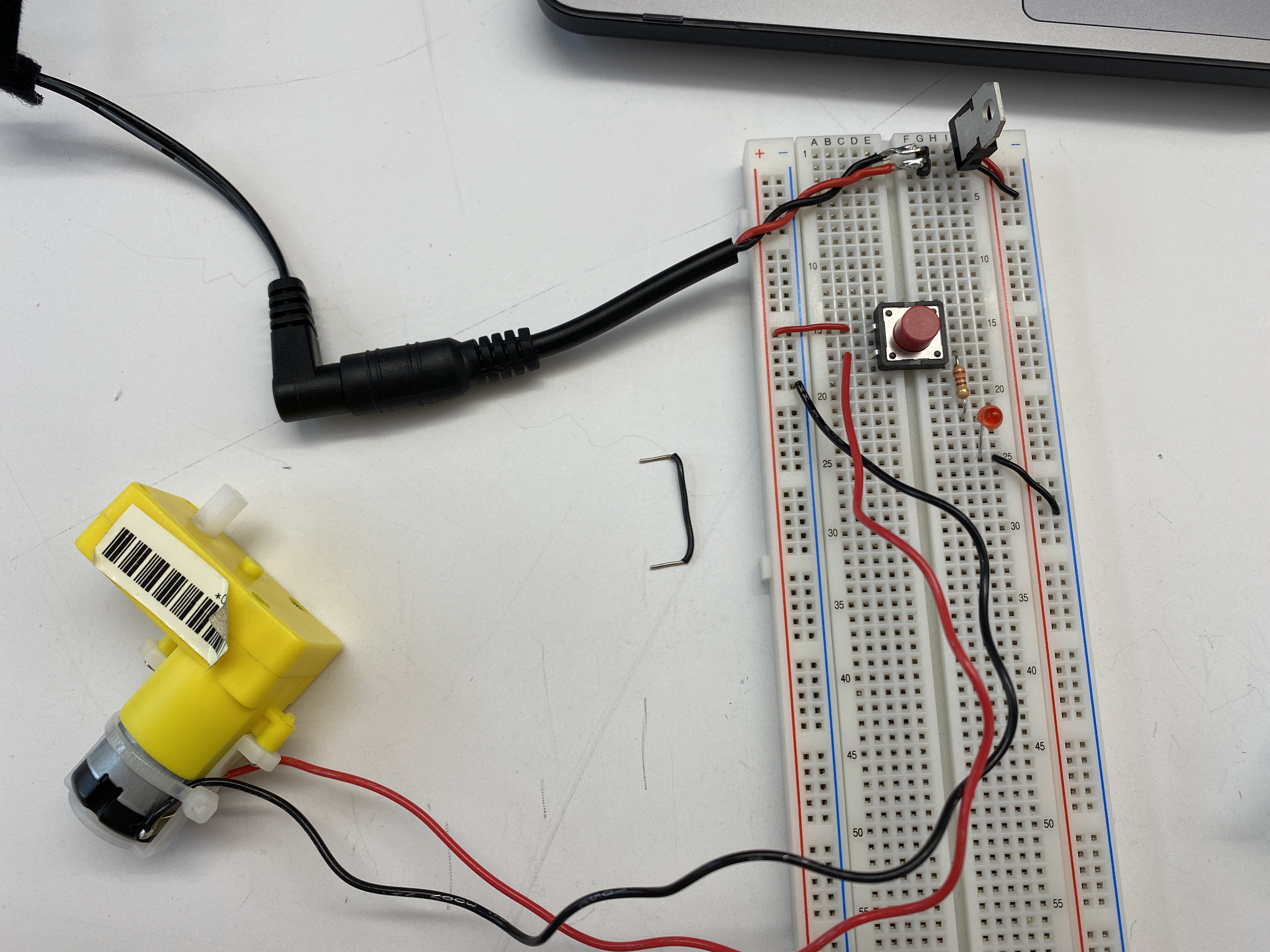
Project 3: Switching a Motor
A motor attached to a switch.
At first I had some issues with this portion of the lab because I just could not get the motor to run.
For a moment, the first motor I was using moved bu then immediately stopped and I was unable to get it working again.
After fussing with it some more, I decided to borrow another motor from the shop, and immediately
I was able to get it to work. So I just came to the conclusion it may have been a bad motor.
A motor and LED both operated by a dual pole switch.
Creative Switch
The Record Stand Light
For my creative switch, I took inspiration from
this stand
I have that is shaped to hold and display a record sleeve while the record spins on my turntable.
I want to recreate this stand so that when a record is place in its slot, a light will turn on.
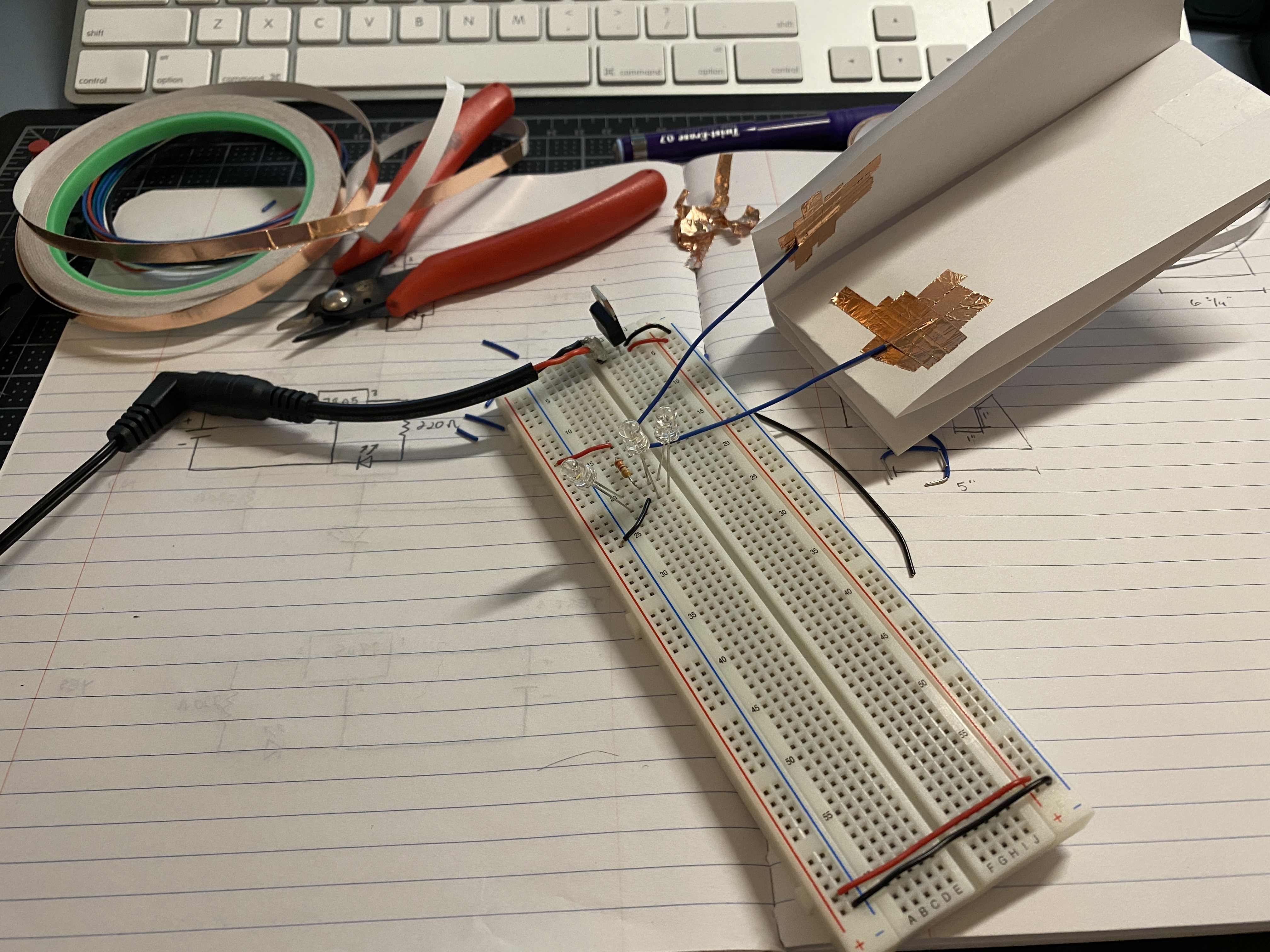
As pictured above, I started off by playing around with other materials to
make a switch sensitive to touch. Here I stuck two wires to a folded piece of
paper with some copper tape to make a switch that would activate the light
when I sandwiched the two sides together. In this circuit, I had three white
LEDs in parallel to all be turned on simultaneously by the switch.
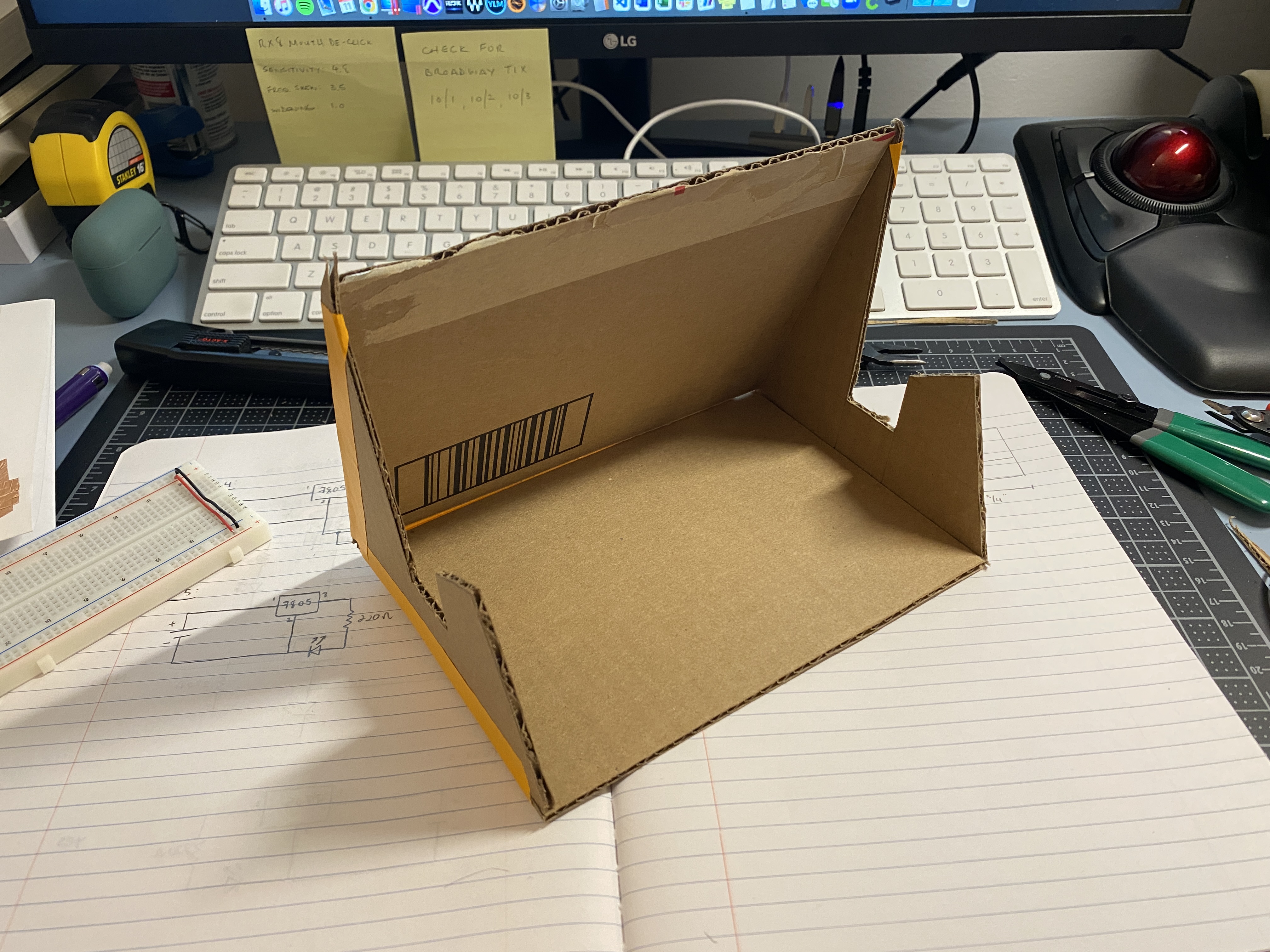
Below I started shaping out a prototype enclosure with cardboard and tape. I
started to play around with cutouts for the LEDs and the DC power supply
port.
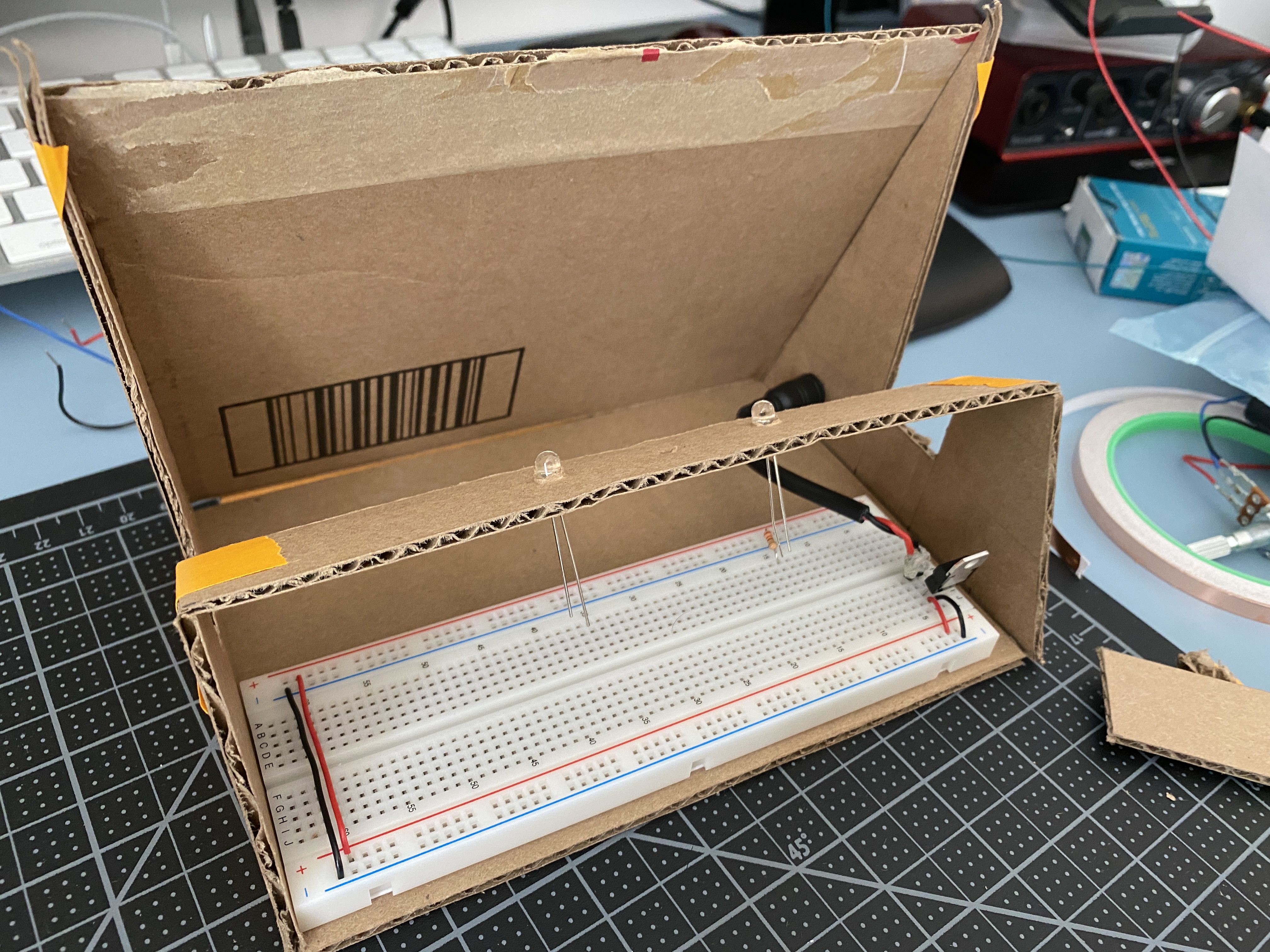
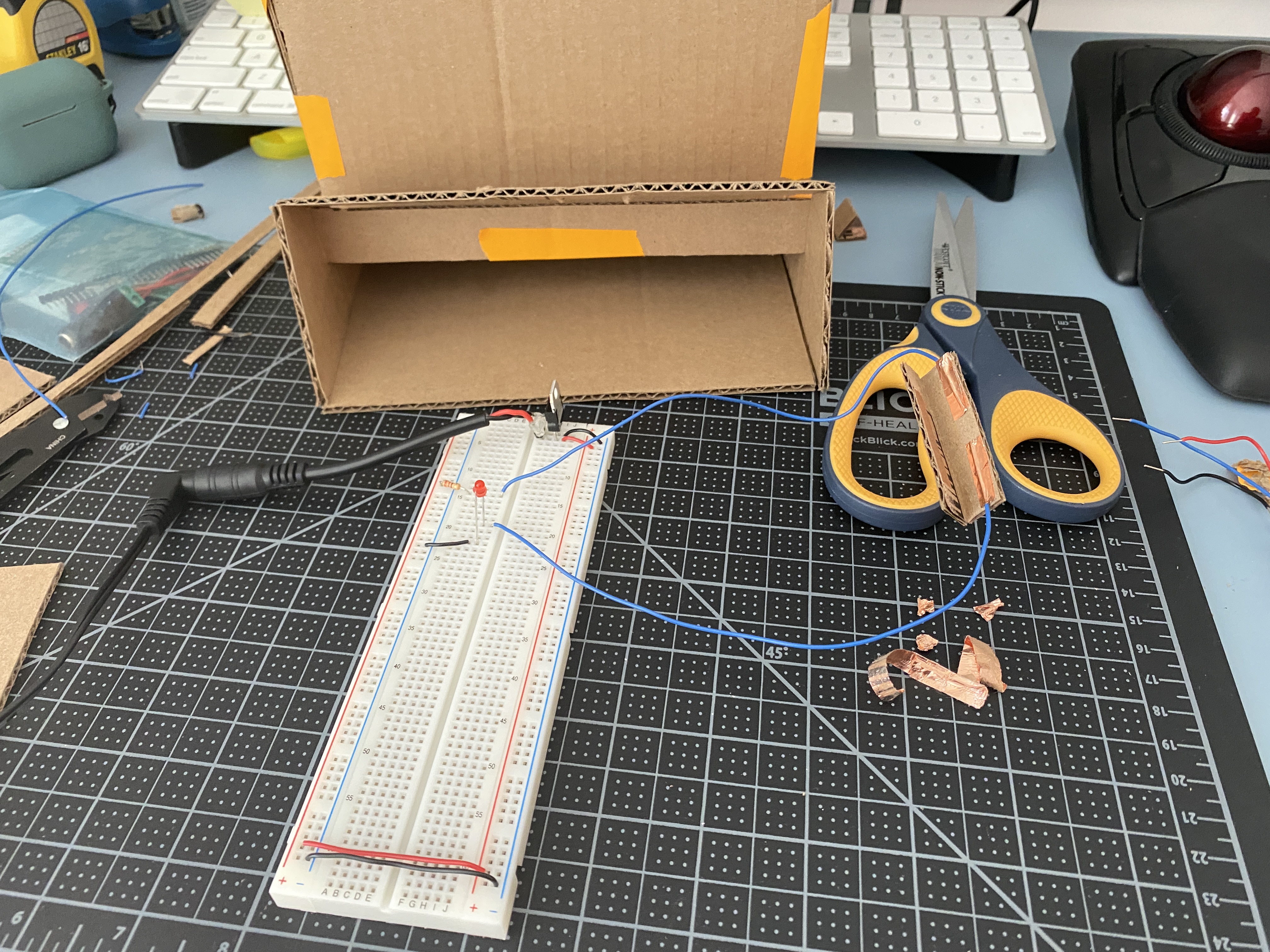
Next, I recreated the switch from above into a smaller shape with some
cardboard so that I can place it in the slot where the record sleeve would sit.
Once I had the connection, I arranged the switch into the prototype and
tested it by actually placing a record. Here it is a bit finicky as the record
needs to be placed in a specific position in order for the switch to stay
closed.
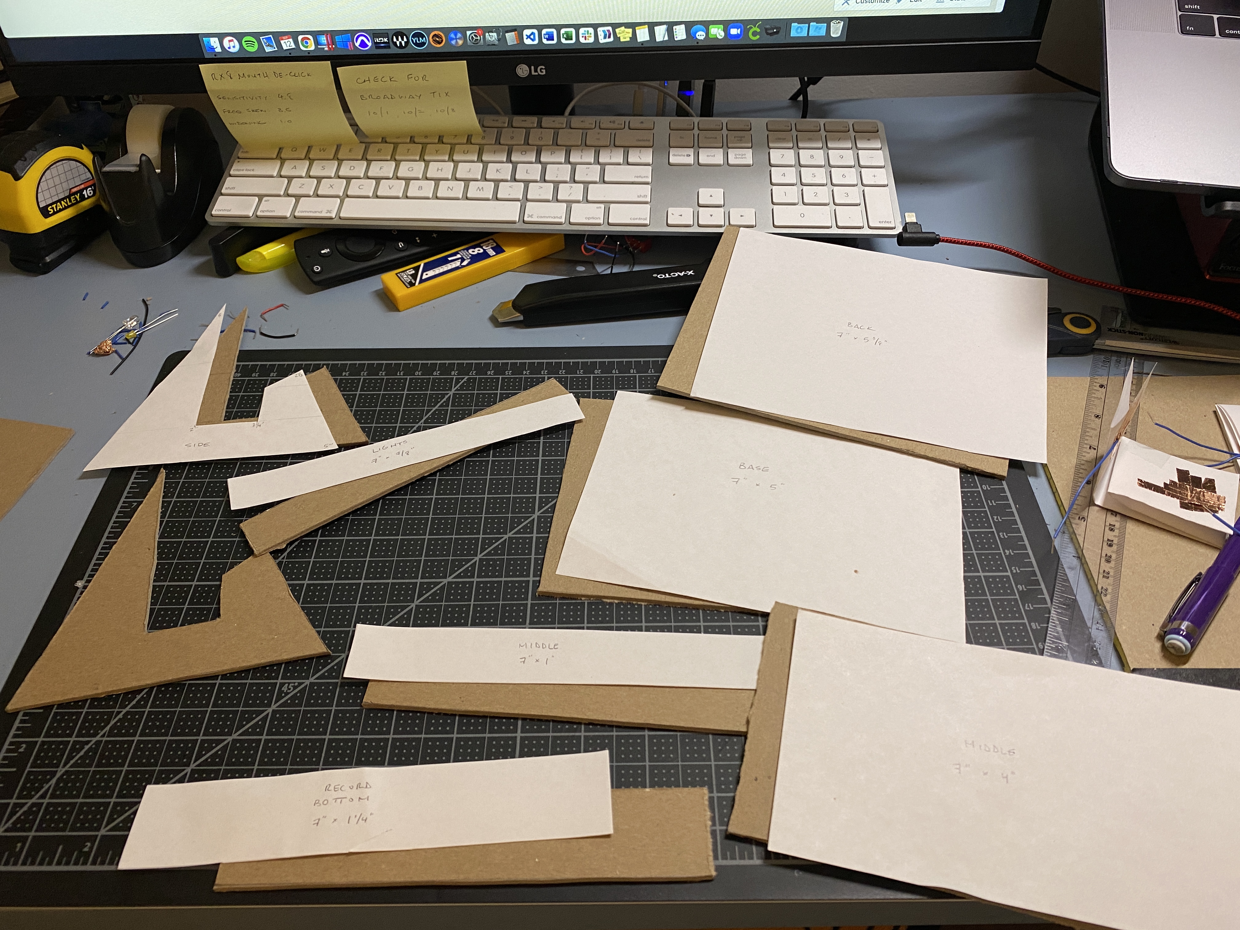
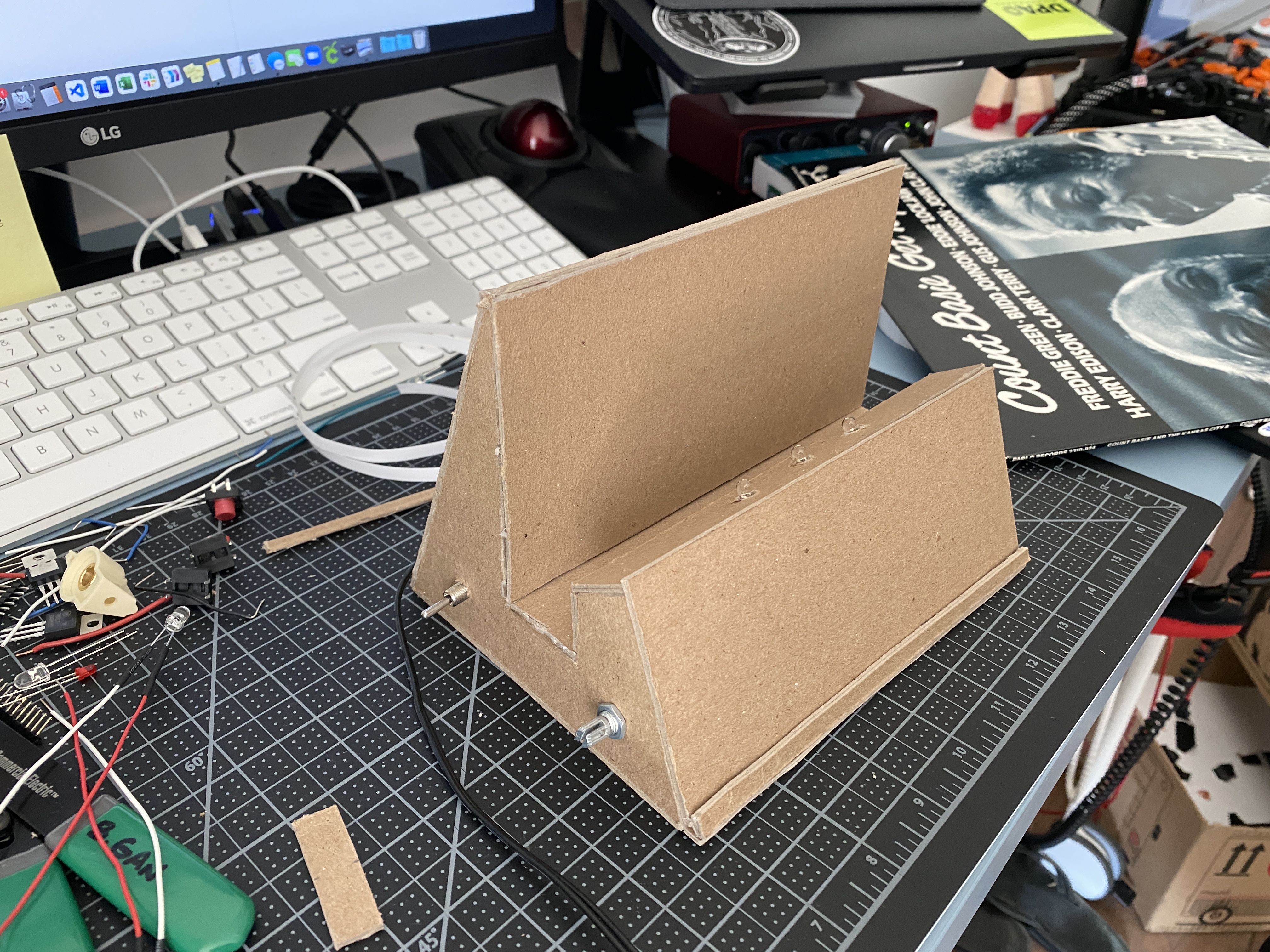
Once I had my prototype enclosure, I cut out pieces for my final enclosure
using what I believe is compressed cardboard …? I’m not sure, I took it from
the free shelf on the floor 🙂
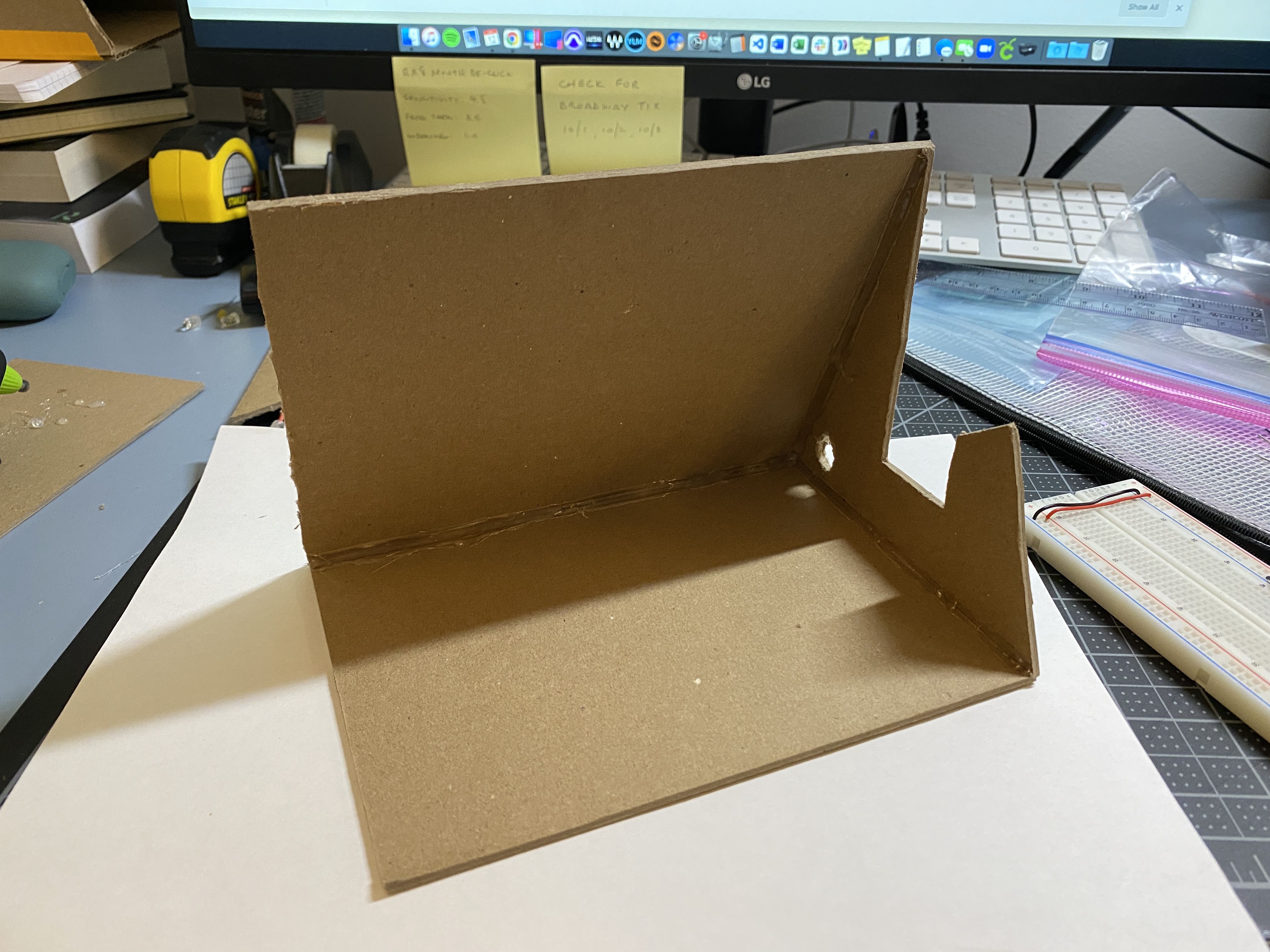
I just used hot glue to bind a few of the sides.
I then played around with some different circuits to ultimately incorporate
three separate switches.
In the figure on the left, I used the press switch along with a potentiometer.
In this circuit the press switch would light up the green LED, and when the
potentiometer was turned on, it would also light up the white LED.
In the circuit on the right, a switch is in line with the potentiometer so that
the switch must be flipped to the on position, and the potentiometer turned
up in order for the LED to light up.
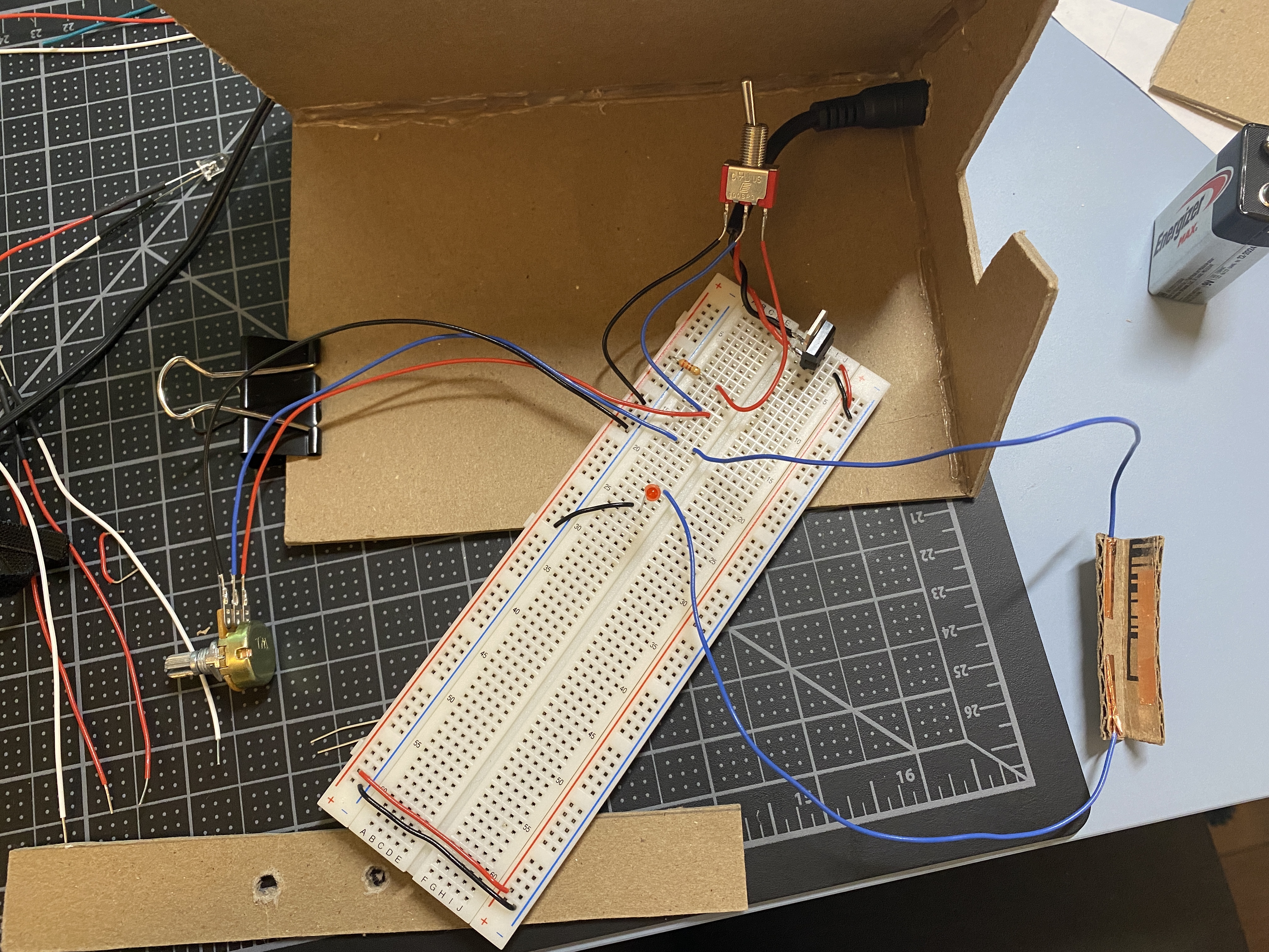
Next, and my final circuit that I decided to use for my creative switch, is a
series that consists of a toggle switch, press switch, and a potentiometer. In
order for the light to turn on everything must be pressed/switched/turned.
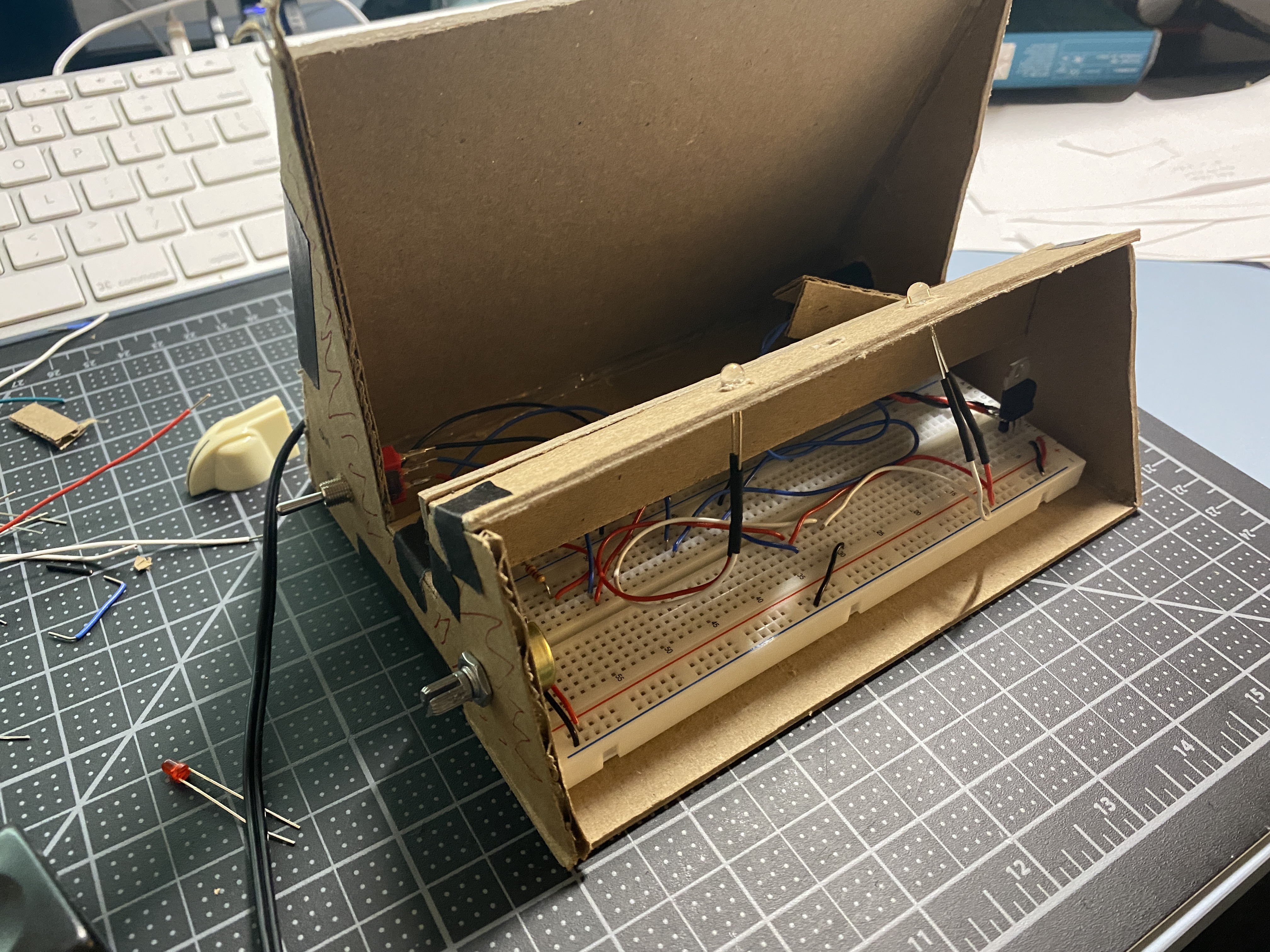
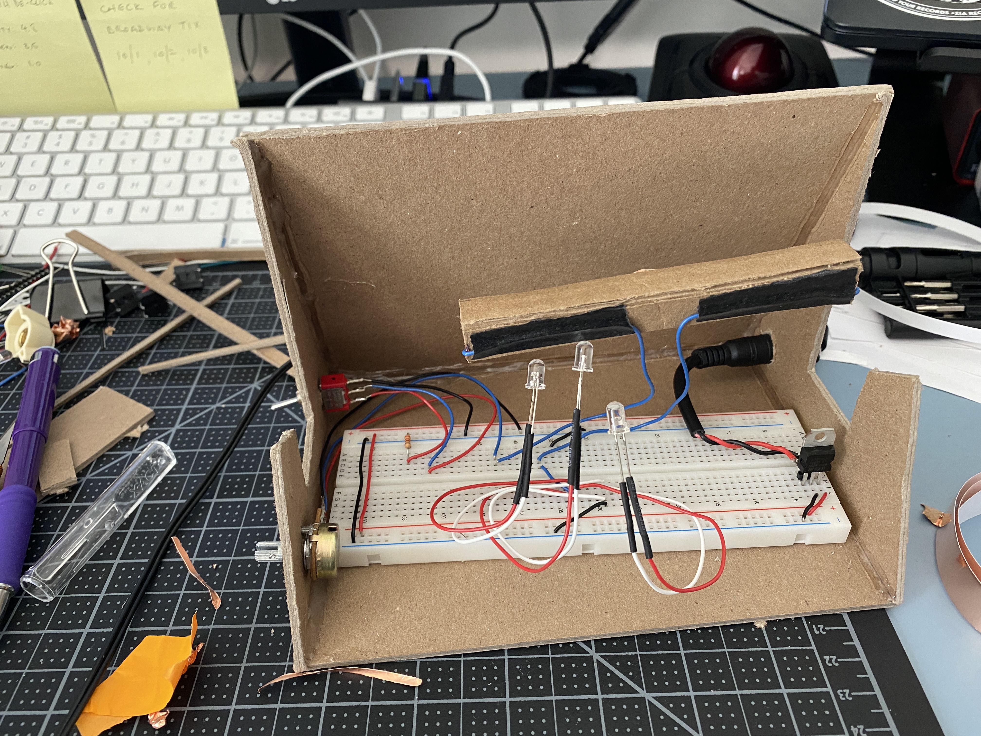
The last bits I needed to do were to finish the enclosure, and all the wiring. I
decided to have three LEDs in parallel, and in order for the LED prongs to
reach the breadboard, I soldered hookup wires to the cathode and anode,
and used heat-shrink over the connections to prevent any shorts.
Before putting all the actual panels together and completing the enclosure, I
partially used bits of my cardboard prototype to make wiring adjustments
before finalizing.
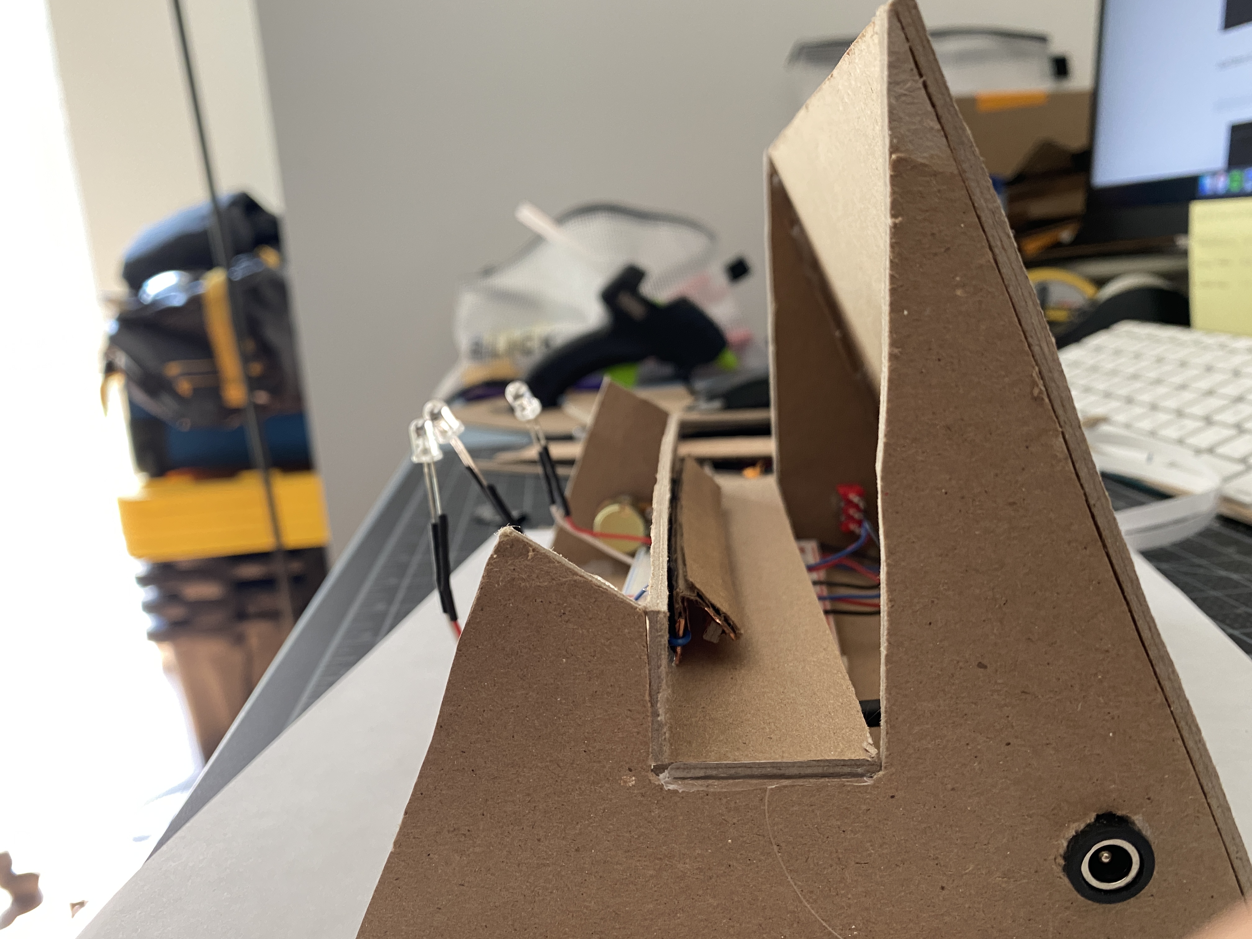
One issue I ran into was activating the press switch. It’s a bit touchy with the
record placement and sometimes the record would have to be in a specific
position in order for the press switch to make the connection. Trying to fix
this issue, I lengthened the press switch, and added a layer to one side,
hoping to increase the surface area that could make the connection
between the two wires.
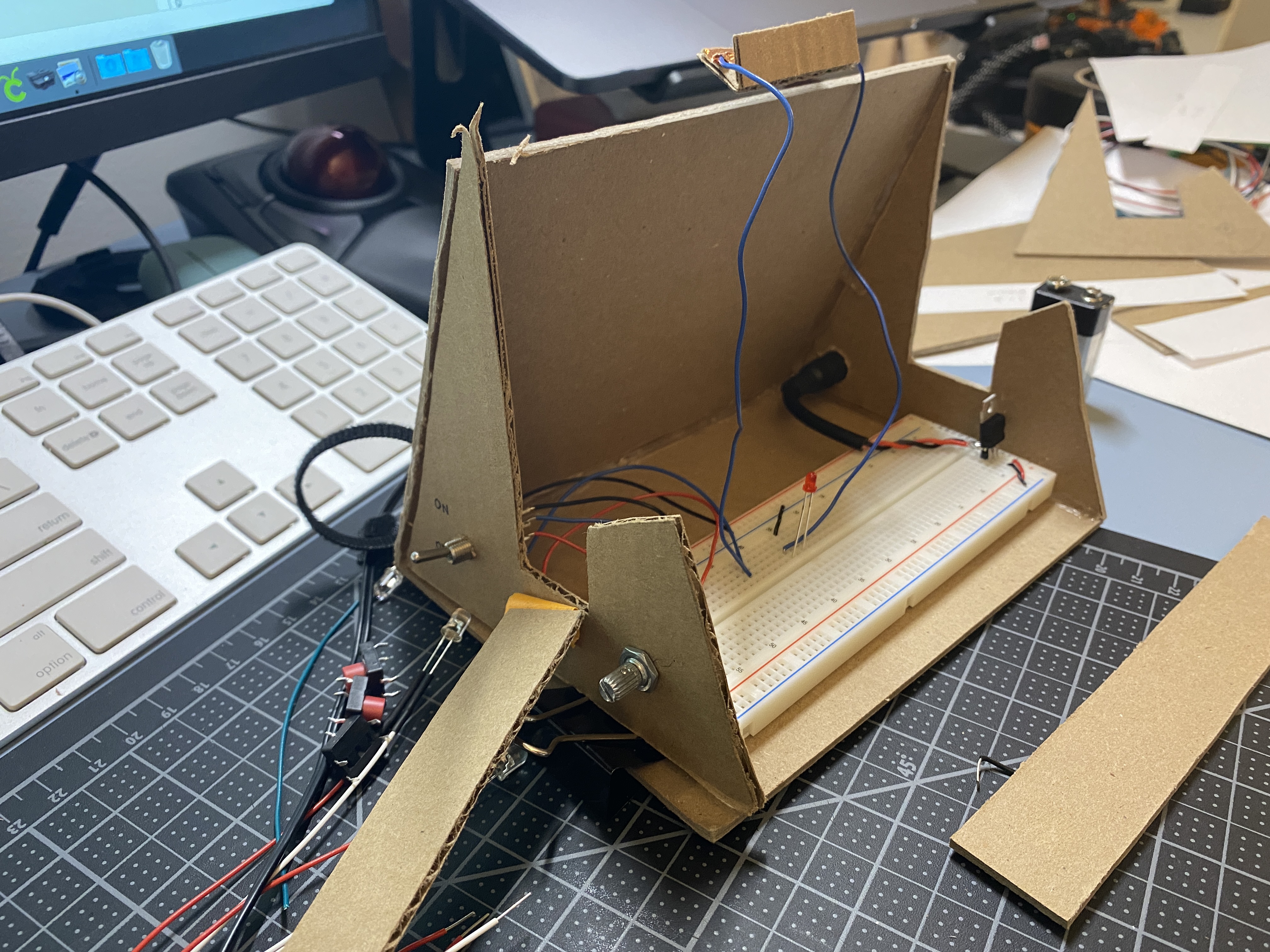
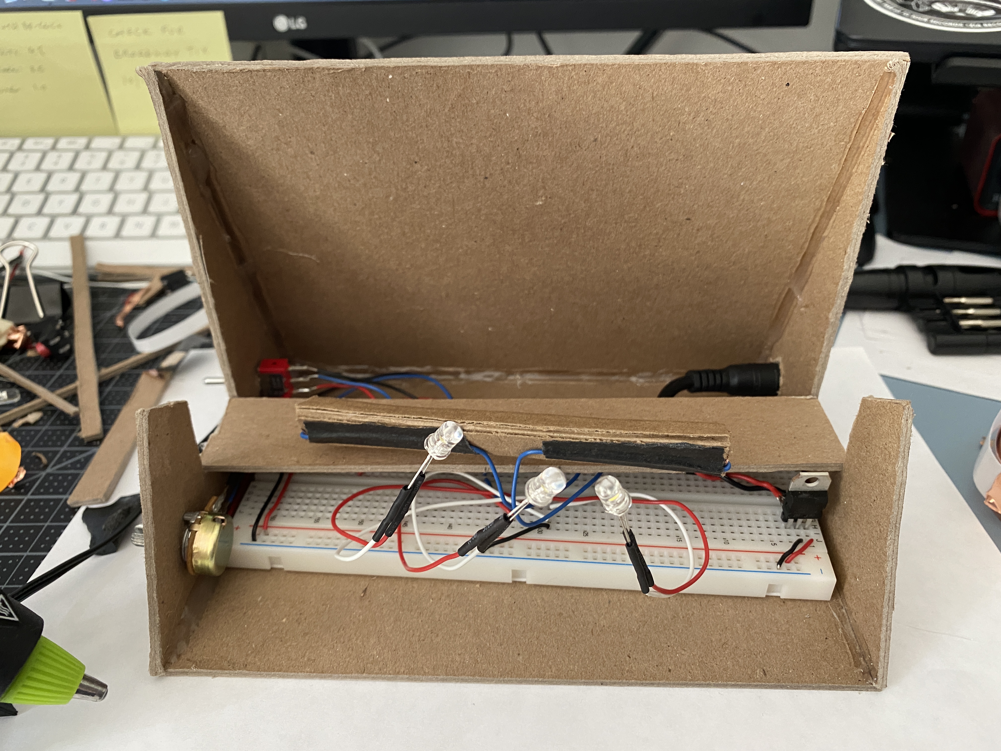
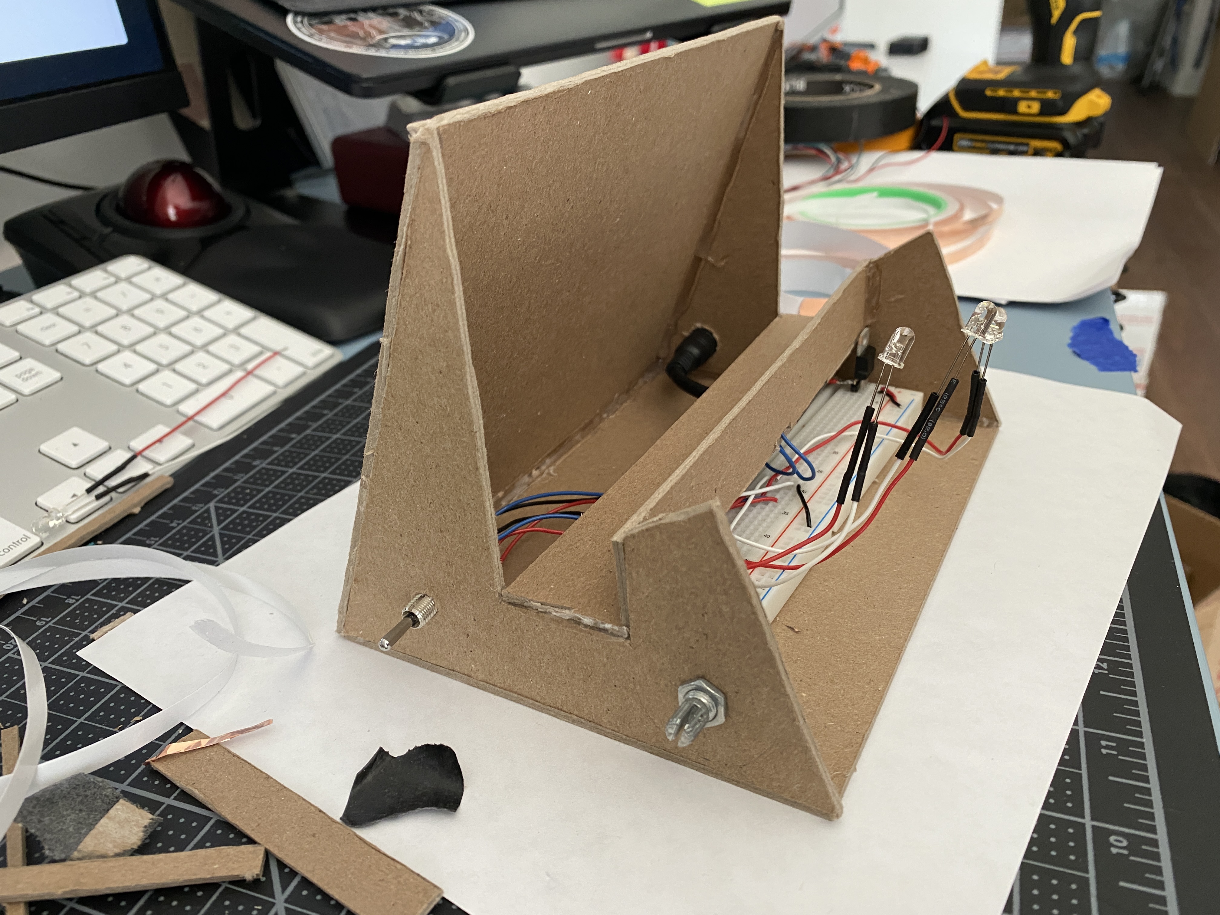
I continued to work on finishing the wiring and adding the rest of the panels to the enclosure.
Below is the final look of the record stand light. A last minute add —
something I almost forgot to do — was to make sure I had a way to get the
breadboard back out without ripping apart the panels, and so I made the
front panel removable.