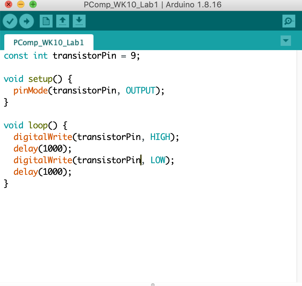
Lab 01: Using a transistor to control high current loads with an Arduino
To start, we had an issue getting the DC motor to work, we believed it may
have been a bad wire. We troubleshooted and made sure all the connections
were correct, then ultimately decided to change the motor for another, and
that ended up working.
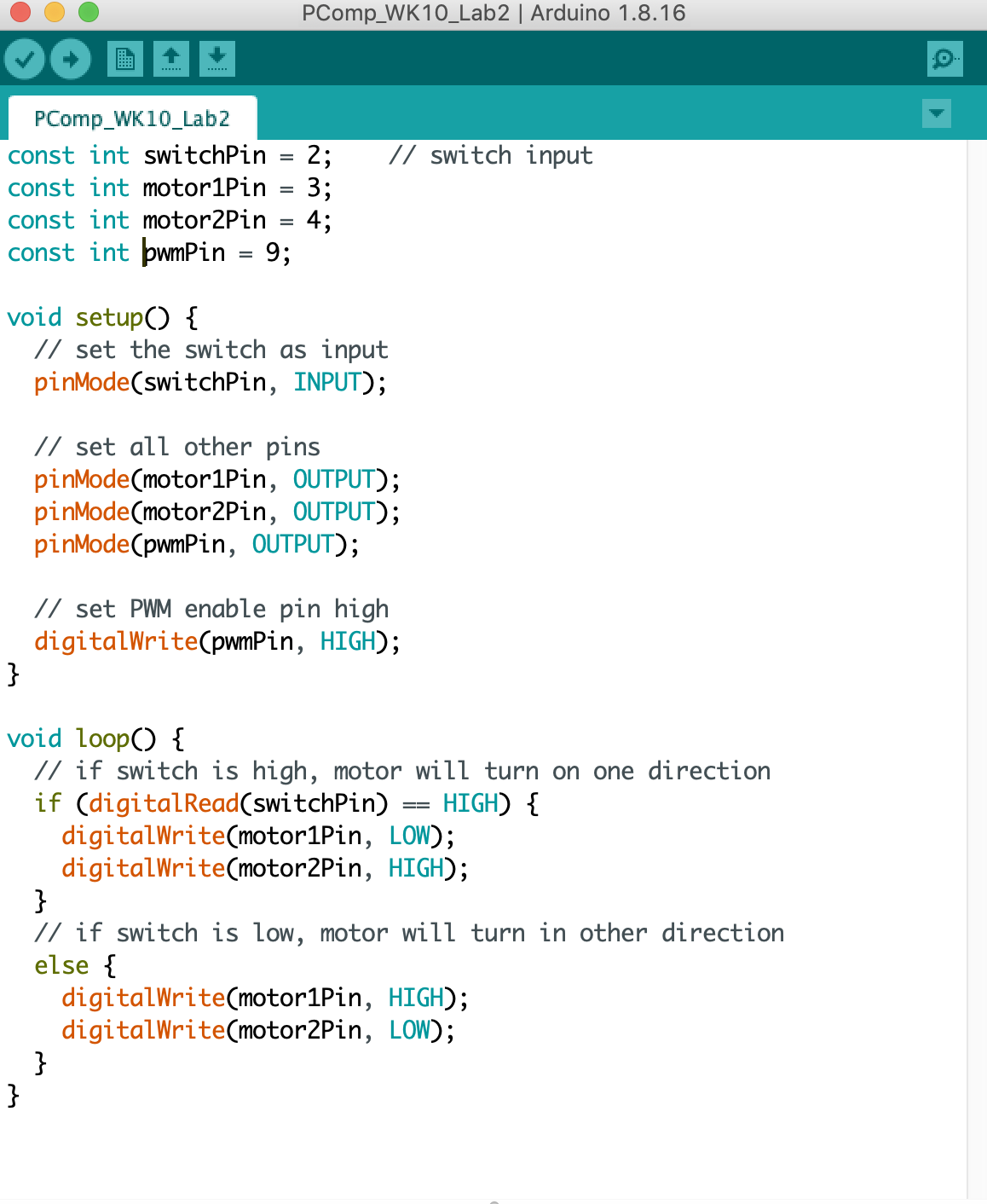
Lab 02: DC motor control using an H-bridge
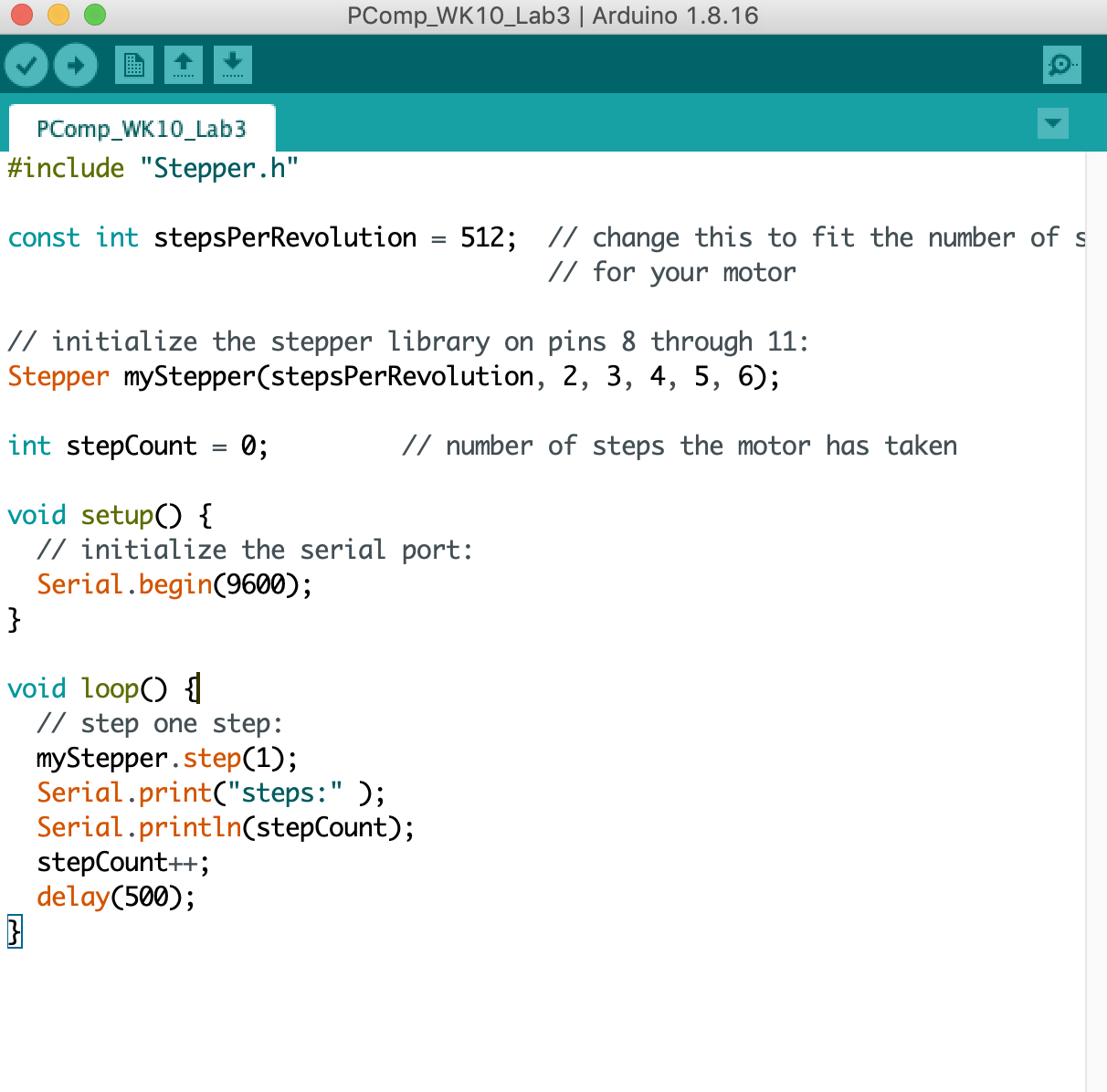
Lab 03: Controlling a stepper motor with an H-bridge
I had some issues with this lab. It was a little hard to translate the schematic
from the lab– there were no more of the H-bridge IC (L293D) chip, so I was
still using the H-bridge TB6612 breakout board from the second lab. Most of the
schematics were using the IC chip, and none of them involved the
Arduino Nano. The very bottom schematic used an Arduino MKR Zero, so I
attempted to translate the pins using that onto my breadboard.
I was unable to get the stepper motor to work. The Arduino serial monitor
was outputting the steps so the code was correct, and the motor did start
to heat up so I know it was receiving voltage, but it didn’t move.
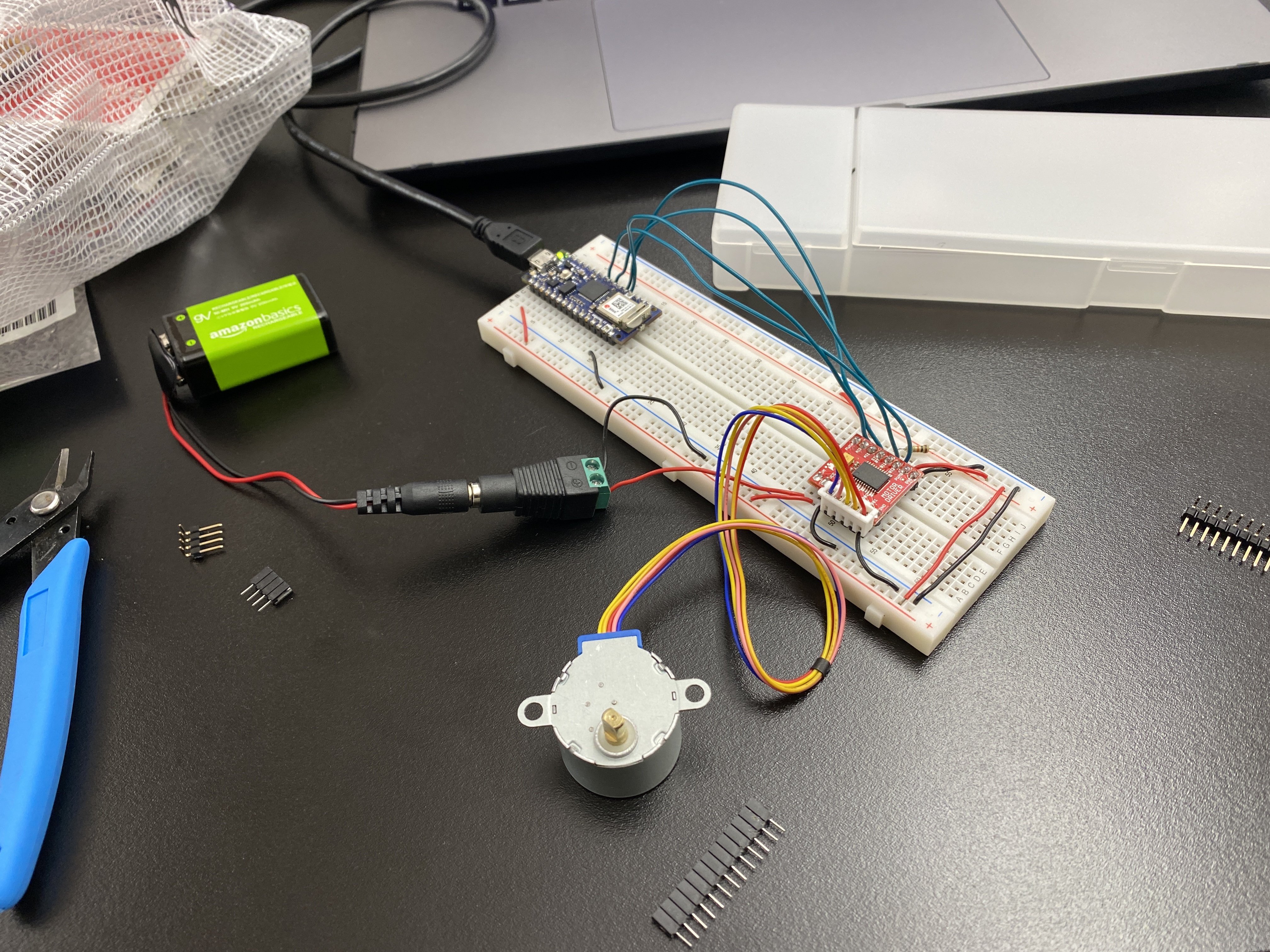
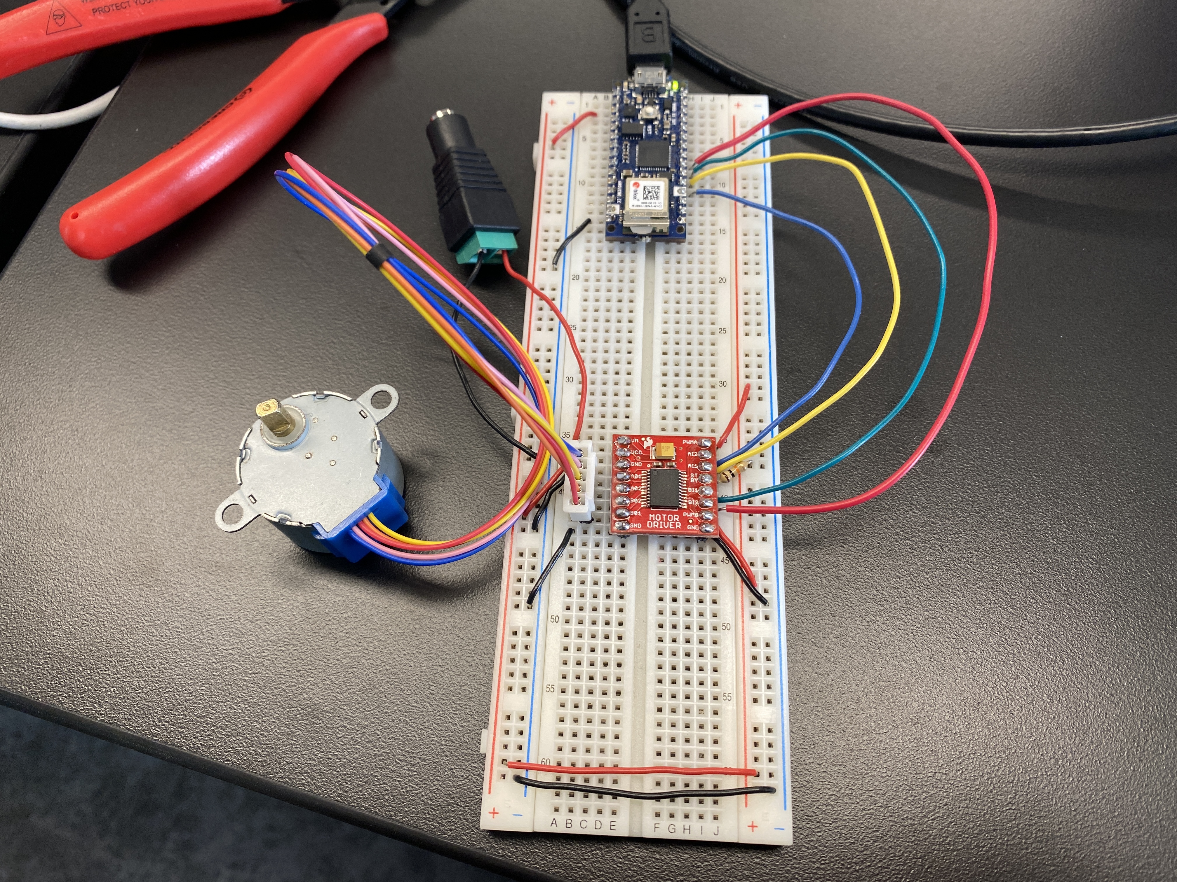
Lab 03 (cont'd): In-class trial
Mo and I attempted the stepper motor lab in class. With Yeseul’s help, it
turns out the color orientation of the wires on the stepper motor from the
shop is different according to the wiring in the schematics on the lab.
It works!
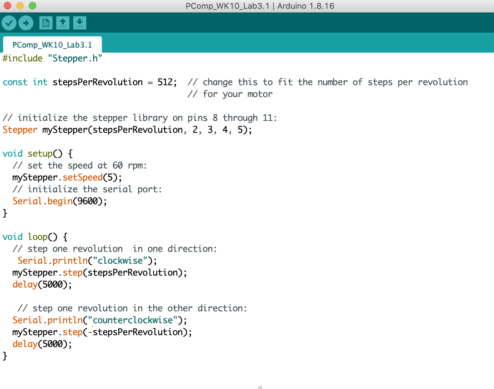
The steps were very slow, so we reduced the delay to 50 milliseconds.
For the second part of this lab, we ran into another issue where the motor
would go counterclockwise, pause for 5 seconds, but then it would continue
in the same direction rather than going clockwise. Yeseul helped us
troubleshoot again and we used her motor, because there is a mismatch
with the leads on the stepper motor we have.